Properly designed fiber optic cables ensure maximum transmission performance and network reliability. Critical design factors include pulling strength limits, bend radius guidelines, water protection, and fire rating compliance, among others. Understanding key cable specifications assists infrastructure planning and successful deployments.
Table of Contents
Pulling Strength
Properly pulling fiber optic cables during installation ensures no damage occurs to the internal glass fibers or their optical transmission capabilities. There are two key pulling strength ratings:
Short-term (installation)
The short-term rating applies temporarily during the installation process. Stresses can occur when:
- Pulling cables through underground ducts or conduits
- Making sharp 90-degree turns
- Passing around reel vaults
- Overcoming back tension on payout reels
“Short term stresses during an installation can be caused by pulling the cable through ducts, around bends, back tension on the payoff reel, etc.”
To prevent fiber damage:
- Use tension monitoring tools and never exceed specified ratings
- Make pulls by hand in slow, steady motions without jerking
- Keep tension to an absolute minimum necessary
Long-term (operating)
Once a cable is fully installed, the long-term rating applies to occasional tension loads in operation.
“Long term tensile strength is the maximum value that a specific cable can withstand after the cable has been installed.”
In conduits, ducts, aerial installations, and ceiling routes, external forces can apply some non-continuous tension loads over decades of operation. However, the cable only needs to withstand very low operational loads without damage or significant optical degradation issues.
Adhere to Manufacturer Limits
- Pull by hand in steady, continuous motions
- Don’t exceed specified limits, which are usually 50-600 lbs
- Use swivel-pulling eyes and tension-monitoring
“The fiber optic cable should be installed using the minimum possible tension,” as per the manufacturer’s guidelines.
Prevent Damage
- Set reel vaults near sharp bends
- Make pulls under two 90° bends maximum
- Separate long runs with intermediate pull boxes
Don’t jerk or pull at extreme angles, which can break internal optical fibers.
Install Properly
Correct installation avoids damaging fibers and maintains optical characteristics. Keep sustained loads well below operational limits, too.
Proper fiber optic cable designs account for both short-term installation and long-term installed maximum pulling strengths when specifying construction, sheath durability, and fiber protection. Following manufacturer guidance prevents both immediate cable damage and future transmission issues.
Bending Radius Limit
The bending radius is the maximum curvature a cable can be bent without causing optical loss or damage. Two key ratings protect cables:
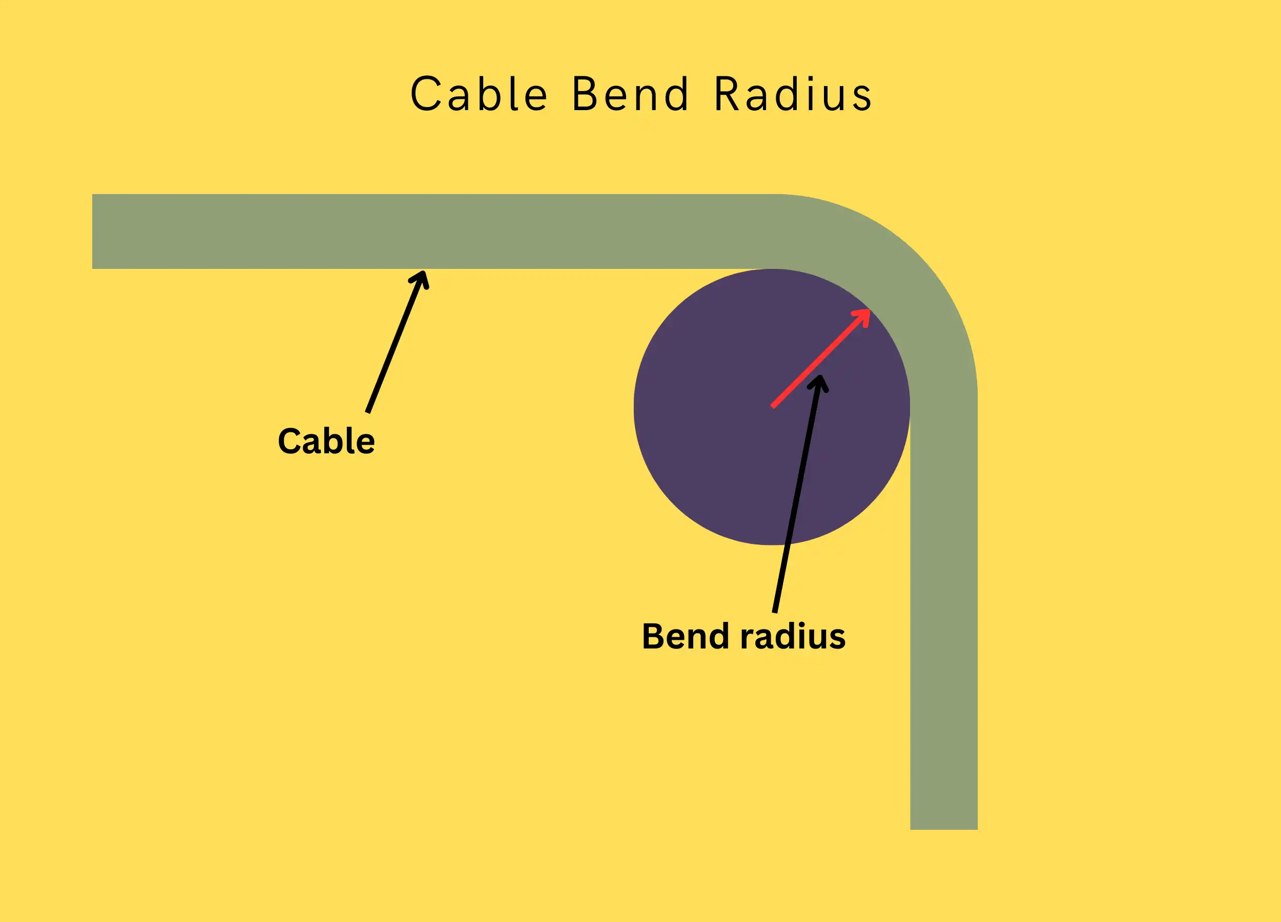
Installation Bend Radius
During installation, while the cable is under tension, the minimum bend radius is 20 times the outer cable diameter. This larger radius prevents:
- Over-bending fibers
- Chronic signal loss
- Fiber microcracks
- Future cable failures
Sharp bends under pull tension strain the glass fibers. Use larger diameter pulleys and sleds through all ducts and conduits.
“20 times the outer cable diameter is minimum bend radius under tension during pulling (short term-during installation)”
Installed Bend Radius
After a cable is installed without pull tension, the minimum bend tightens to 10 times the cable diameter.
“10 times the cable diameter is minimum bend radius when not under tension, (long term-installed).”
The cable retains some flexibility to handle turns and corners without degrading optical performance. However, avoid sharp 90-degree building entries or ceiling routes. Use flexible conduit bending.
Try out our bend radius calculator here
Bend Radius Protection
Additional installation practices prevent over-bending:
- Hand-pull cables to control curvatures.
- Use swivel-pulling eyes to prevent twisting.
- Don’t exceed two 90-degree bends per pull.
- Install intermediate pull boxes to separate runs.
Careful bend radius adherence maintains cable and optical fiber integrity.
Protection Against Water and Moisture
Water and moisture pose significant threats to optical fiber performance and infrastructure longevity. Outdoor and premise cables require robust protection solutions:
Water Blocking Materials
Cables utilize internal components to block water penetration fully:
- Gel filling – A non-hydroscopic flooding compound injected into the cable core that prevents water intrusion into free spaces.
- Absorbent Powders – Layers of absorbent substances inside cable jacketing that soak up moisture.
- Water-Blocking Tapes – Specialty tapes wound with powdered superabsorbent polymers.
“It starts with a moisture resistant jacket, usually PE (polyethylene), and a filling of water-blocking material. Either a gel, or absorbent tape powder is used to prevent water from entering the cable and causing harm to the optical fibers.”
Performance Standards
Stringent industry testing protocols ensure cable water protection:
- GR-20-CORE – Telcordia generic requirements for OSP fiber cables from -40C to +85C
- IEC 60794-1-2 – Environmental testing, including temperature cycling, water penetration, and moisture resistance
Fully validated designs guarantee moisture can’t reach internal glass fibers.
Handling Considerations
Proper installation and termination prevent moisture from entering from open cable ends:
- Thoroughly clean fibers before splicing or insertion into frames
- Keep work areas dust-free and debris-free
- Re-seal enclosures and closures after access
Following best practices sustains long-term water-blocking performance and optical reliability.
Crush and Impact Loads
Cables installed in ducts, conduits, aerial strands, buried installations, and building pathways risk significant crush loads and impacts. Proper design prevents optical damage during deployment and operation:
Crush Resistance
Crush testing under EIA-455-41A verifies cables survive up to 1,500 lbs/ft compressive forces without fiber damage or transmission loss.
This accounts for:
- Rocks and debris in buried conduits
- Vehicles driving over subsurface routes
- Heavy static or dynamic loads
Special reinforcements handle extreme pressures:
- High crush strength metallic armor
- Aramid yarns for tensile reinforcement
- Extra thick abrasion-resistant outer jacketing
“Crush can be defined as a fiber optic cable’s ability to withstand, or recover from (or both), the effects of a compressive force.”
Impact Resistance
Repeated impact testing per IEC-60794-1-2 simulates:
- Rock strikes during cable pulls
- Tool or hardware drops during handling
-routine abuse
Durable construction prevents fiber fractures, cracks, or jacket slits which degrade optical performance.
Real-World Survivability
Cables installed in demanding environments must withstand continuous mechanical risks. Fibers transmit reliably despite significant and frequent exterior pressures across decades of linking global information networks.
Fire Code Ratings
Indoor cables carry NEC fire ratings per intended deployment area. Outdoor cables lack ratings when routed through buildings.
Rating Levels
Plenum – Deployed in air handling spaces
Riser – Runs vertically between floors
General Purpose – All other areas
NEC (National Electrical Code) ratings:
- OFNP/OFCP – Plenum
- OFNR/OFCR – Riser
- OFNG/OFCG – General Purpose
“Plenum cables are subject to the most stringent testing of any of the cables rated by the NEC. They are rated for both flammability and smoke generation.”
Substitution Rules
- Higher ratings can sub for lower
- Plenum substitutes for Riser and General
- Outdoor cables are limited to 50 ft indoors.
Correct ratings reduce fire spread. Don’t violate intended deployments.
Hybrid Cabling
Bring outdoor cables indoors using a hybrid cable with the following:
- PE jacket
- UL-rated PVC indoor jacket
The outdoor PE jacket doesn’t affect indoor fire protection.
Adhere to all NEC fire codes for safely routing fiber optic cables through buildings. Limit unrated outdoor cable runs.
Cable Color Codes
Standardized color codes uniquely identify cable types and individual fibers. Consistent labeling prevents improper connections.
Outer Jacket Colors
Jacket colors indicate intended cable routing:
| Fiber Type | Color Code | |
|---|---|---|
| OM1 62.5/125µm Multimode | Orange | |
| OM2 50/125µm Multimode | Orange | |
| OM3 50/125 µm (850 nm Laser-Optimized) Multimode | Aqua | |
| OM4 50/125µm (850 nm Laser-Optimized) Multimode | Aqua/ | Violet |
| OM5 50/125µm (850 nm Laser-Optimized) Multimode | Lime Green | |
| 100/140µm Multimode | Orange | |
| OS1/OS2 Single-mode | Yellow | |
| Polarization Maintaining single-mode | Blue | |
“Outdoor cables are generally black but premises cables are color-coded Optical fibers are often distinguished from one another by color-coded jackets, buffers or coating on each optical fiber.”
Individual Fiber Coding
Individual fibers follow EIA/TIA-598-D standards:
- Orange: 62.5/125μm OM1 multimode
- Aqua: 50/125μm OM3 laser-optimized multimode
- Yellow: OS1/OS2 single-mode
- Blue: PM single-mode fiber
Colors identify the core size and fiber type for proper connections.
Buffer Color Sequence
12-fiber subsets use repeating color sequence:
| Fiber | Color Code | |
| 1 | Blue |
 |
| 2 | Orange |
 |
| 3 | Green |
 |
| 4 | Brown |
 |
| 5 | Slate |
 |
| 6 | White |
 |
| 7 | Red |
 |
| 8 | Black |
 |
| 9 | Yellow |
 |
| 10 | Violet |
 |
| 11 | Rose |
 |
| 12 | Aqua |
 |
“According to EIA/TIA-598, inner fibers are color coded in a group of 12 fibers and they are counted in a clockwise direction.”
Beyond the 12th strand, fibers identify with some tracers. Here are the fiber strand colors 13 to 24
| Fiber | Color Code | |
| 13 | Blue with black tracer |
 |
| 14 | Orange with black tracer |
 |
| 15 | Green with black tracer |
 |
| 16 | Brown with black tracer |
 |
| 17 | Slate with black tracer |
 |
| 18 | White with black tracer |
 |
| 19 | Red with black tracer |
 |
| 20 | Black with white tracer |
 |
| 21 | Yellow with black tracer |
 |
| 22 | Violet with black tracer |
 |
| 23 | Rose with black tracer |
 |
| 24 | Aqua with black tracer |
 |
Summary
The safe installation and reliable performance of fiber optic cables depends on several critical design factors:
Pulling Strength – Cables can withstand 50-600 lbs short-term during installation. Long-term tension is lower once deployed. Always monitor pull tension to prevent fiber damage.
Bend Radius – Use large 20x cable diameters when pulling, down to 10x post-installation. Prevent sharp turns during handling. Separate runs with intermediate boxes.
Water Protection – Block moisture ingress completely with gel-filling, tapes, and polyethylene jacketing. Meet industry spread and environmental standards.
Crush Resistance – Withstand over 1,500 lbs/ft compressive loads. Reinforce with aramid yarns and thick jackets. Pass impact testing per standards.
Fire Ratings – All indoor cables must meet plenum, riser, or general-purpose NEC codes for flame spread and smoke density.
Color Coding – Outer jackets indicate the environment. Individual fiber colors identify the core size and fiber type for safe connections.
Adhering to design limits, construction standards, and handling procedures sustains long-term cable functionality, meeting optical networking necessities.
FAQ
What are the factors to consider when selecting fiber optic cable?
Selecting the perfect fiber optic cable isn’t just about specs; it’s about matching your needs. Consider the transmission distance, required bandwidth, budget, and installation environment. Multimode offers shorter-range flexibility, while single-mode shines for long distances and high bandwidth. Think carefully about what matters most!
What two specifications must be considered when specifying optical cable?
Don’t get bogged down by endless details. Two key specs rule the roost: core diameter (affects mode type and bandwidth) and refractive index (determines light propagation). Mastering these unlocks the door to choosing the right fiber for your mission.
What is the most significant consideration when installing optical fiber cables?
The biggest consideration when laying down fiber is minimizing signal loss. Plan your route wisely, avoid tight bends, and choose the right connectors. Remember, a smooth journey for light means a smooth journey for your data.
What are the technical specifications of fiber?
Dive deeper into the technical specifications that make fiber tick. Attenuation (signal loss per unit distance), refractive index (how light bends within the core), and bandwidth (data carrying capacity) are your new best friends. Understanding these unlocks the true potential of your fiber network.
Can fiber optics be run above ground?
Don’t limit yourself to the underground! Fiber optic cables can soar above the ground, too, conquering long distances and even harsh environments. Just make sure you choose cables with UV-resistant jackets and appropriate strength for aerial installations.