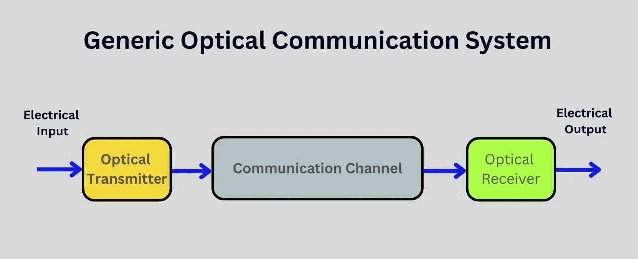
Fiber optic communication systems use light pulses to transmit information over long distances via optical fibers. These systems rely on three vital components working together – the communication channel, the optical transmitter, and the optical receiver.
The optical fiber cable itself makes up the channel for transporting signals with far higher bandwidths than electrical cables over similar distances. Additionally, inline devices help boost signals and extend the reach of optical networks.
The optical transmitter handles the crucial conversion of electrical signals used by network equipment to optical signals that can traverse the optical fiber using light-emitting components like laser diodes.
At the receiving end, the optical receiver performs the reverse operation, transforming the incoming optical signals back to electrical signals for other networking hardware to process.
Let’s explore these components further to understand fiber optic communication.
Table of Contents
Fiber Optic Communication System Components
Communication Channel
The communication channel refers to the full optical link from transmitter to receiver, including the optical fiber cabling and other inline devices.
Optical Fibers
Optical fibers allow the transmission of signals over long distances, from a few hundred meters to hundreds of kilometers, with far higher bandwidths than electrical cables over similar distances.
Silica glass (SiO₂) based optical fibers can carry signals with minimum loss compared to electrical cables, allowing very high-speed communication links spanning cities or even countries.
Optical Amplifiers
Optical amplifiers work by using a pump laser to supply energy to a section of doped fiber known as the gain medium. As signals pass through this gain medium, they stimulate the emission of additional photons. This reinforcement of the optical signal combats attenuation loss in the fiber.
Some types of optical amplifiers include:
- Erbium-doped fiber amplifiers (EDFAs) – Use erbium-doped silica fiber as a gain medium. EDFAs are widely used to boost signals in C-band and L-band wavelengths for long-distance telecom networks.
- Semiconductor optical amplifiers (SOAs) – Use semiconductor materials providing high optical gain in a small device. SOAs work for a wider range of wavelengths.
Overall, optical amplifiers enable extending repeaterless links to over 6000 km while supporting high data rates by overcoming loss during light propagation in fibers.
Repeaters and Regenerators
Regenerators feature additional signal correction capabilities compared to basic repeaters. They help counteract impairments like:
- Dispersion – Different spectral components travel at different speeds in optical fiber, causing signal distortion.
- Attenuation – Absorption and scattering losses reduce signal strength over distance.
- Noise – Additional irregular fluctuations are introduced during propagation.
Powerful error correction coding techniques help regenerators overcome noise and some dispersion while restoring signals to full power levels after amplification.
Overall, regenerators enable reliable high-speed communication over thousands of kilometers through cumulative amplification and signal cleanup at periodic intervals.
Optical Joints
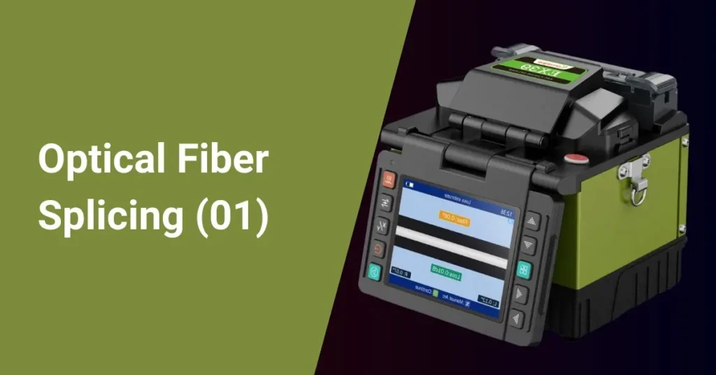
Optical joints have two main types – mechanical splices and fusion splices.
Mechanical splices use precision ferrules and adhesive for joining. However slight misalignment often leads to higher losses, around 0.5 dB typically.
Fusion splicing provides lower loss durable joints by fusing or welding glass fibers using electric arcs. But it requires skilled technicians and sophisticated equipment. The best fusion splices have losses below 0.1 dB.
Optical Connectors
Some common types of optical connectors include:
- ST connectors – Bayonet style twist-locking connectors
- SC connectors – Push-pull style connectors snapped into place
- LC connectors – Small form factor connectors widely used in high-density hardware
Choosing the right connector type is vital for noise-free coupling between transmitter/receiver modules, optical amplifiers and test equipment in the optical link.
Optical Splitters and Couplers
Optical splitters divide a single input optical signal into multiple (2 to 64 typically) output fibers. They allow cost savings by enabling a single transmitter to reach multiple receivers in passive optical networks.
Meanwhile, optical couplers combine signals from multiple input fibers onto a single output fiber. This facilitates converging signals from multiple transmitters onto a single fiber for composite transmission.
Both passive optical splitters and couplers help efficiently distribute and route optical signals.
Optical Transmitter
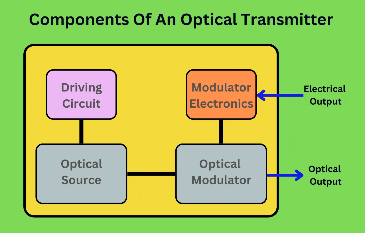
The optical transmitter handles the vital conversion of electrical signals to optical signals for transmission over fiber optic networks.
Key components:
- Optical source – Light emitting components like laser diodes or LEDs.
- Laser diodes provide high power, narrow spectrum light for long distances and high bandwidth transmission. Types include Fabry-Perot (FP), distributed feedback (DFB) and vertical-cavity surface-emitting lasers (VCSELs).
- LEDs feature wider optical spectra, which is useful for short-reach links up to 100 m. Superluminescent diodes (SLDs) give a medium range.
- Driving circuit – Drives optical source by modulating injection current based on input electrical signal.
- Cooling unit – Maintains operating temperature for stable performance.
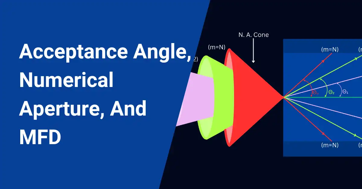
- Channel coupler – Coupling components like lenses focus light into the fiber with minimal loss.
Output power, wavelength, modulation speed, distance reach etc., vary across transmitters targeting different network applications from backplane to long-haul.
Optical Receiver
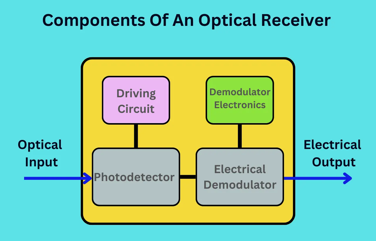
Stationed at the far end, optical receivers have the crucial job of detecting the transmitted signal amidst impairments after fiber traversal and converting it back into the electrical domain.
Key components:
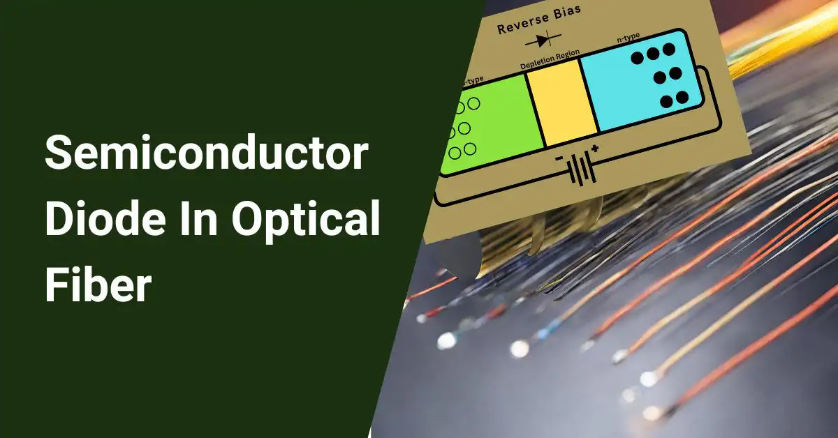
- Photodetector – Photodiodes, phototransistors, and PMTs can convert optical signals to electrical current through the photoelectric effect. Pros and cons exist for each detector type.
- Transimpedance amplifier (TIA) – Basically converts the generated photocurrent to a usable voltage signal. Provides initial amplification of the received signal.
- Limiting amplifier – Additional amplification while removing noise to give full digital logic level signals.
- Signal processing unit – Decodes and processes signal as needed by electrical interface while checking for transmission errors.
Sensitivity, dynamic range, bandwidth, noise figure etc., represent key parameters that determine overall receiver performance in reliably detecting signals after fiber optic transmission across required distances.
Optical Transceiver
Optical transceivers integrate both transmitting and receiving capabilities in a single module to enable two-way optical communication.
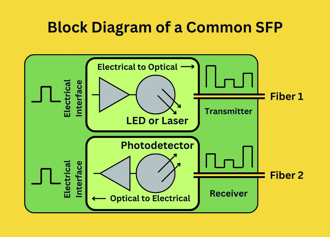
Benefits include:
- Compact form factor suitable for pluggable and embedded applications
- Reduced hardware complexity with integration for manufacturing and cost savings
- Hot-swappability provisions for device or service changes without disrupting networks
Various standard form factors exist to meet different network needs – data rate, link distance, number of channels, wavelengths etc. Some examples are:
- Small Form Factor Pluggable (SFP, SFP+)
- 10 Gigabit Small Form Factor Pluggable (XFP)
- 100 Gigabit Pluggable (CFP, CFP2)
- Quad Small Form Factor Pluggable (QSFP)
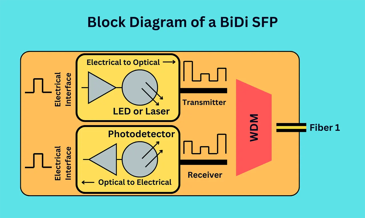
Bidirectional transceivers further save on hardware with a single port for simultaneous transmit and receive. They utilize wavelength division multiplexing for two-way communication over a single fiber strand.
Summary
The synchronized functioning between optical communication components enables reliable high-bandwidth transmission through fiber optic networks for meeting various connectivity needs.
While silica glass optical fibers provide a low-loss channel for light wave guidance using total internal reflection, amplifiers and regenerators help combat signal degradation over ultra-long distances.
Optical transmitters and receivers handle the crucial electrical-optical-electrical signal conversion at cable ends, tailored for diverse applications.
And hot-pluggable optical transceiver modules integrate transmission and reception functions for straightforward network upgrades.
So each element in these fiber optic links has an important role to play in jointly providing high-speed, long-reach optical transmission systems underlying modern communication.
FAQ
What are the main components of a fiber optics communication system?
The main components of a fiber optics communication system include the optical fiber itself (core, cladding, and coating), optical amplifiers, repeaters, optical joints, optical connectors, and optical transmitters and receivers that convert electrical signals into light and vice versa.
What is the basic fiber optic communication system?
The basic fiber optic communication system consists of the optical fiber (core, cladding, and coating), optical transmitters, and optical receivers. These components work together to transmit data using light pulses.
What are the major components used in an optical transmitter?
The major components used in an optical transmitter include:
∎ Electrical-to-optical converter: Converts the electrical signal into an optical signal (usually using a laser or LED).
∎ Driver circuitry: Provides power and controls the converter for modulation and data encoding.
∎ Lens and collimator: Focuses and aligns the light from the converter into the fiber core.
∎ Temperature control: Ensures stable operation and long lifespan of the transmitter components.
How does the optical fiber communication system work?
The information, typically digital data, is converted into electrical pulses by the transmitter. These pulses control the intensity or modulation of the light source (laser or LED). The modulated light pulses travel through the fiber core, bouncing off the cladding due to internal reflection. At the destination, the receiver detects the light pulses and converts them back into electrical signals, which are then decoded back into the original information.
Which is the key component of an optical receiver?
The key component of an optical receiver is the photodetector. This device converts the incoming light pulses into electrical current. Common types of photodetectors include PIN diodes and avalanche photodiodes.


