Photodetectors are the unsung heroes in the world of optoelectronics. They serve as the eyes that convert light into electrical signals, enabling a vast array of applications from telecommunications to remote sensing.
Among the various types of photodetectors, PIN (Positive-Intrinsic-Negative) diodes reign supreme due to their versatility, efficiency, and cost-effectiveness. In this article, we’ll dive into the key parameters that define a photodetector’s performance, exploring the intricacies of responsivity and quantum efficiency.
Table of Contents
Responsivity
What is Responsivity?
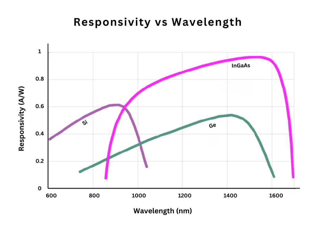
Responsivity measures how efficiently a photodetector converts light into electrical current. It’s expressed in amperes per watt (A/W), and it varies with wavelength.
Think of a photodiode as a tiny garden where light is the sunshine, and the electrical current is the flourishing crop. A high responsivity means the photodiode can produce a bountiful harvest of current from the light it receives.
Responsivity Champions
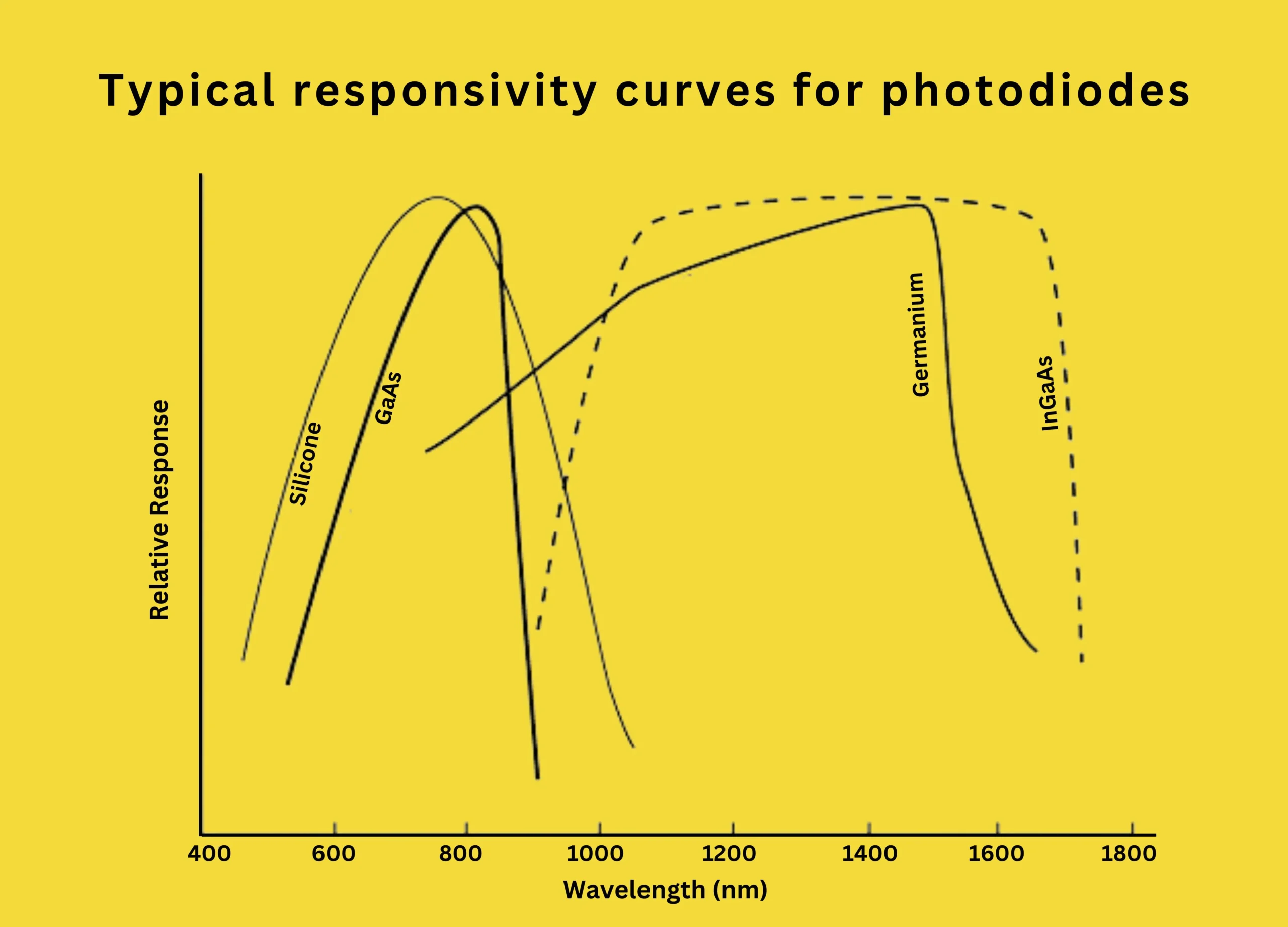
Different materials excel at different wavelength ranges due to their unique properties. Here are the champions:
Silicon Photodiodes
- Rule the roost in the visible and near-infrared range (400-1100 nm)
- Peak responsivity: 635 mA/W at 900 nm
- Even at 850 nm (a common wavelength for data transmission), responsivity remains near its peak.
Indium Gallium Arsenide (InGaAs) Photodiodes
- Shine in the longer wavelength territory (900-1700 nm)
- Responsivity: Above 500 mA/W across this broad range
- Do not peak sharply like silicon but offer a broader response curve
Why Responsivity Matters
The higher the responsivity, the more current you can generate from a given amount of light. This is crucial in applications where every photon counts, like fibre optic communications or low-light imaging. Understanding responsivity allows engineers to select the right photodetector material for their specific wavelength requirements.
Quantum Efficiency
What is Quantum Efficiency?
Quantum efficiency (QE) measures how well a photodetector converts incoming photons (light particles) into electrical charge carriers (electrons and holes). It’s like the photodetector’s batting average – a higher QE means more photons successfully make it to the base, contributing to the electrical current.
QE can be expressed as a decimal value between 0 and 1 or as a percentage. A QE of 1 (or 100%) would be a perfect game, where every absorbed photon creates an electron-hole pair. In reality, a typical QE of 0.7 (70%) means only 7 out of every 10 photons score a hit.
Quantum Efficiency and Responsivity: Partners in Crime
Quantum efficiency and responsivity are closely linked through a simple equation:
\(Responsivity=\frac{eλ}{hc}QE\)
Here, e is the electron charge, λ is the wavelength, and h and c are fundamental constants. By optimizing quantum efficiency, you can boost the responsivity and overall light-to-current conversion efficiency of the photodetector.
Material Matters
Different materials excel at different wavelengths due to their varying bandgaps – the minimum energy required to excite an electron.
- Silicon, with its wider bandgap, reigns supreme in the visible and near-infrared range.
- Narrower bandgap materials like InGaAs take the lead at longer wavelengths.
Quantum Efficiency Values
- Ideal Case (QE of 1 or 100%): Every absorbed photon generates an electron-hole pair, resulting in maximum efficiency.
- Typical Case (QE around 70%): For every 10 incoming photons, only 7 contribute to the electrical current.
Quantum efficiency applies to primary electrons created by photon absorption, not secondary carriers generated by collision ionization within the material.
Important parameters of detectors
| Parameter | Silicon | Germanium | InGaAs | |||
| PIN | APD | PIN | APD | PIN | APD | |
| Wavelength range (nm) | 100-1100 | 800-1800 | 900-1700 | |||
| Peak (nm) | 900 | 830 | 1550 | 1300 | 1300 (1550) | 1300 (1550) |
| Responsivity p (A/W) | 0.6 | 77-130 | 1.65-0.7 | 3-28 | 0.63-0.8 (0.75-0.97) | |
| Quantum Efficiency (%) | 65-90 | 77 | 50-55 | 55-75 | 60-70 | 60-70 |
| Gain (M) | 1 | 150-250 | 1 | 5-40 | 1 | 10-30 |
| Excess Noise Factor (x) | - | 0.3-0.5 | - | 0.95-1 | - | 0.7 |
| Bias Voltage (-V) | 45-100 | 220 | 6-10 | 20-35 | 5 | <30 |
| Dark Current (nA) | 1-10 | 0.1-1.0 | 50-500 | 10-500 | 1-20 | 1-5 |
| Capacitance (pF) | 1.2-3 | 1.3-2 | 2-5 | 2-5 | 0.5-2 | 0.5 |
| Rise Time (ns) | 0.5-1 | 0.1-2 | 0.1-0.5 | 0.5-0.8 | 0.06-0.5 | 0.1-0.5 |
By understanding responsivity and quantum efficiency, engineers can optimize the light-to-current conversion process, enabling applications that demand high sensitivity and precision.
Dark Current
Dark current is the photodetector’s version of background noise – an unwanted electrical current that flows even when there’s no light shining on the device. It’s like a pesky little stream that muddies the waters, making it harder to detect the true signal generated by light.
Understanding the Cause
The main culprit behind dark current is thermal excitation. Visualize the photodiode material as a microscopic stadium filled with vibrating electrons. As the temperature rises, these electrons become more energetic, and some manage to overcome the barriers within the device, contributing to the dark current flow.
Temperature Tantrums
Dark current thrives in warm environments. Even a small rise in temperature can cause a significant jump in dark current levels. This increase is typically exponential, meaning the warmer it gets, the more electrons have enough energy to sneak past the barriers and contribute to the unwanted current flow.
Material Matters
The material used in the photodetector significantly impacts dark current levels. Here’s how different materials stack up:
- Silicon Photodiodes: With a wider bandgap, silicon makes it harder for thermal energy to excite electrons, resulting in lower dark current levels, especially at shorter wavelengths.
- Germanium (Ge) and InGaAs Photodiodes: These materials have narrower bandgaps, making them more susceptible to thermal excitation and leading to higher dark current levels compared to silicon. However, their superior sensitivity at longer wavelengths might make them the preferred choice for specific applications despite the higher dark current.
Minimizing the Impact
Minimizing dark current is crucial for accurate light detection, especially in low-light conditions. Engineers employ various strategies to keep this unwanted guest at bay:
- Choosing photodiodes with low inherent dark current characteristics
- Minimizing the operating temperature through cooling techniques or placing the photodetector in a cool environment
- Employing biasing techniques to reduce the impact of dark current on the overall signal
Minimum Detectable Power
The minimum detectable power is like the photodetector’s hearing threshold – it determines the faintest whisper of light it can pick up amidst the background noise. This parameter defines the sensitivity of the photodetector, ensuring it can detect even the weakest light signals reliably.
Noise Floor: Quantifying the Minimum Detectable Power
The minimum detectable power is directly related to the noise floor of the photodetector, which is the ratio of the total noise current to the responsivity.
Noise Sources:
- Dark Current: A significant contributor to the noise floor, acting as constant background chatter.
- Thermal Noise: Random electron motion due to temperature, creating a low hum.
- Shot Noise: Statistical variation in current flow, like occasional bursts of noise.
Initial Estimation with Dark Current
For initial assessments, using the dark current alone to estimate the noise level of the floor can provide a good starting point. Since the dark current is often the dominant noise source at low light levels, it gives a preliminary sense of the overall noise level.
Beyond Dark Current: A Comprehensive Approach
However, for a more accurate picture, engineers must consider all relevant noise sources, especially at higher light levels where dark current becomes less dominant.
| Noise Source | Description | Impact on Minimum Detectable Power |
|---|---|---|
| Dark Current (I_dark) | Leakage current due to thermal excitation | Dominant noise source at low light levels |
| Thermal Noise | Random fluctuations due to temperature | Increases with temperature, significant at higher light levels |
| Shot Noise | Statistical variation in current flow | Important at all light levels, independent of light level |
By understanding the minimum detectable power and optimizing the noise floor, engineers can ensure that even the faintest light signals are not lost in the background noise, enabling applications that demand high sensitivity and precision.
Response Time
Response time is the photodetector’s version of a sprinter’s reaction time – it measures how quickly the device can respond to changes in light intensity and produce a corresponding electrical signal.
A fast response time is crucial for applications that involve rapidly modulated light signals, such as high-speed optical communications or real-time imaging.
Rise Time and Fall Time
The response time is typically specified in terms of two values:
- Rise Time: The time it takes for the output signal to go from 10% to 90% of its peak value after the light is turned on.
- Fall Time: The time it takes for the output signal to drop from 90% to 10% when the light is turned off.
Limiting Factors
Transit Time of Charge Carriers
The rise time is primarily limited by the transit time of charge carriers (electrons and holes) within the photodetector. It’s like the time it takes for the sprinter to accelerate from the starting blocks to full speed.
Applying a higher bias voltage can act like a tailwind, slightly speeding up the carriers and resulting in a faster rise time.
RC Time Constant
The RC time constant, determined by the load resistance and diode capacitance, can also create a bottleneck, limiting the bandwidth even with a fast rise time.
Bandwidth Connection
Interestingly, the response time is intimately linked to the usable bandwidth of the photodetector.
The faster the response time, the wider the bandwidth, allowing the photodetector to accurately follow higher frequency light modulations.
Quantifying Bandwidth
Here are two ways to estimate the bandwidth:
- From Rise Time (tr):
Bandwidth = 0.35 / tr
- From RC Time Constant:
Bandwidth = 1 / (2π * RL * Cd)
Where RL is the load resistance, and Cd is the diode capacitance.
Typical Values
- Rise Times: Range from 0.5 nanoseconds to tens of nanoseconds, influenced by bias voltage.
- Fall Times: These are not always specified and are related to the recombination process within the depletion region.
By understanding both the rise time and the RC time constant, engineers can optimize the usable bandwidth of the photodetector, ensuring it can keep up with the demands of high-speed applications.
Conclusion
Photodetectors are the unsung heroes of the optoelectronics world, converting the language of light into electrical signals that power countless applications. By understanding key parameters like responsivity, quantum efficiency, dark current, minimum detectable power, and response time, engineers can unlock the full potential of these remarkable devices.
Whether you’re designing a high-speed fiber optic communication system, a low-light imaging sensor, or a cutting-edge remote sensing technology, selecting the right photodetector with optimized characteristics is crucial for success. So, the next time you marvel at the incredible feats of modern technology, remember to raise a toast to the humble photodetector – the silent guardian that makes it all possible.
FAQ
What is the most common photodetector?
The most common photodetector is the PIN photodiode, offering a good balance of performance characteristics and ease of use.
What is the output of a photodetector?
The output of a photodetector is an electrical current proportional to the intensity of the received light. This current can then be amplified and processed by electronic circuits for further use.
What does a photodetector detect?
Photodetectors primarily detect light. Their spectral response determines which wavelengths they are sensitive to. They can detect the presence, intensity, and sometimes even the modulation of light, depending on the application.
What is the difference between a photodiode and a photodetector?
While often used interchangeably, there is a slight distinction. A photodetector is a broader term encompassing any device that converts light into an electrical signal. A photodiode is a specific type of photodetector that uses a diode structure to achieve this conversion. Photodiodes are very common and offer various functionalities within the photodetector category.
What are some emerging trends in photodetector technology?
The field of photodetector technology is constantly evolving. Here are a couple of interesting trends:
◉ Nanophotonic Photodetectors: These utilize nanostructured materials to achieve enhanced light absorption and potentially higher sensitivity.
◉ Integration with Electronics: Integrating photodetectors directly with electronic circuits on a single chip can lead to miniaturized, high-performance optoelectronic devices.