An optical fiber cable is a complex structure designed to protect fragile glass fibers that transmit digital data using light signals. This advanced cabling solution allows fast, secure data transfer and telecom over long distances. Understanding the components within a fiber optic cable enables proper selection for installation needs.
A fiber cable contains up to hundreds of incredibly thin glass fiber cores within protective layers. Surrounding layers cushion from crushing forces and prevent moisture damage during handling or underground burial. Cables installed outdoors or spanning kilometers also have reinforcing strength members to bear tension loads. Additional enhancements like ripcords facilitate jacket removal for splicing or repairs.
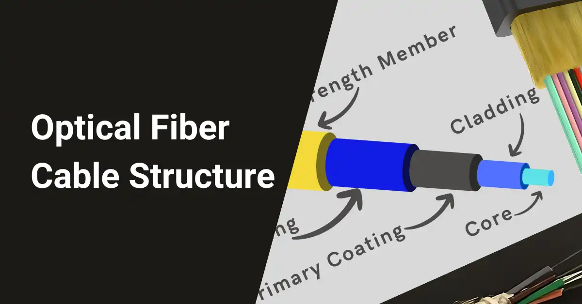
Five vital components comprise a fiber optic cable:
- Core
- Cladding
- Coating
- Strength member
- Cable jacket
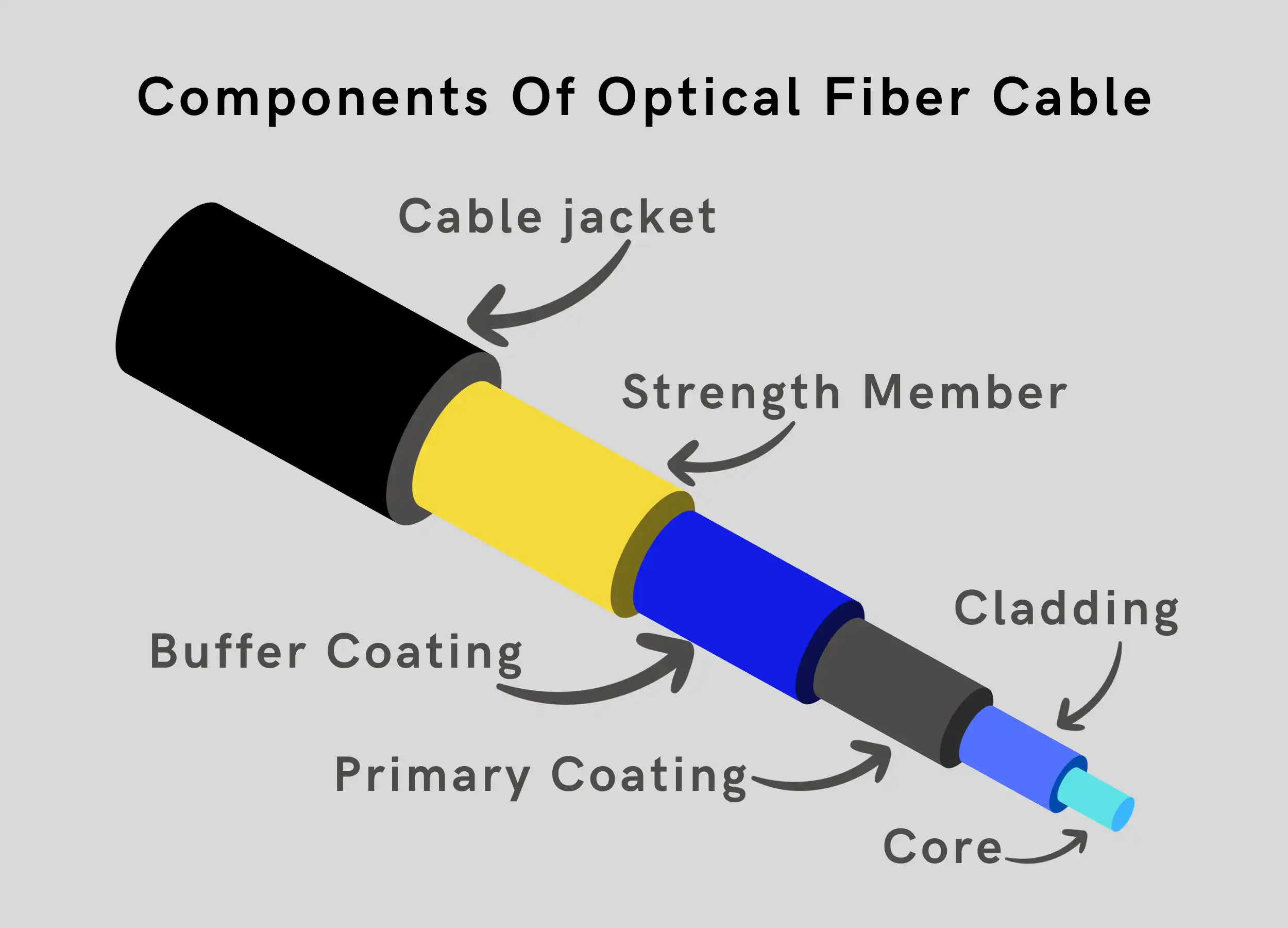
Table of Contents
Core
The core carries data-encoded light through the glass fiber using the principle of total internal reflection. A core’s refractive index exceeds that of the cladding around it. When light reaches this interface at a shallow angle, it bounces back into the core – enabling data transmission over long distances with very little loss.
Material: Core glass contains high-purity silica dioxide with enhancing dopants like germanium to boost the refractive index. Some fibers utilize plastic polymer cores in cost-sensitive short-range links.
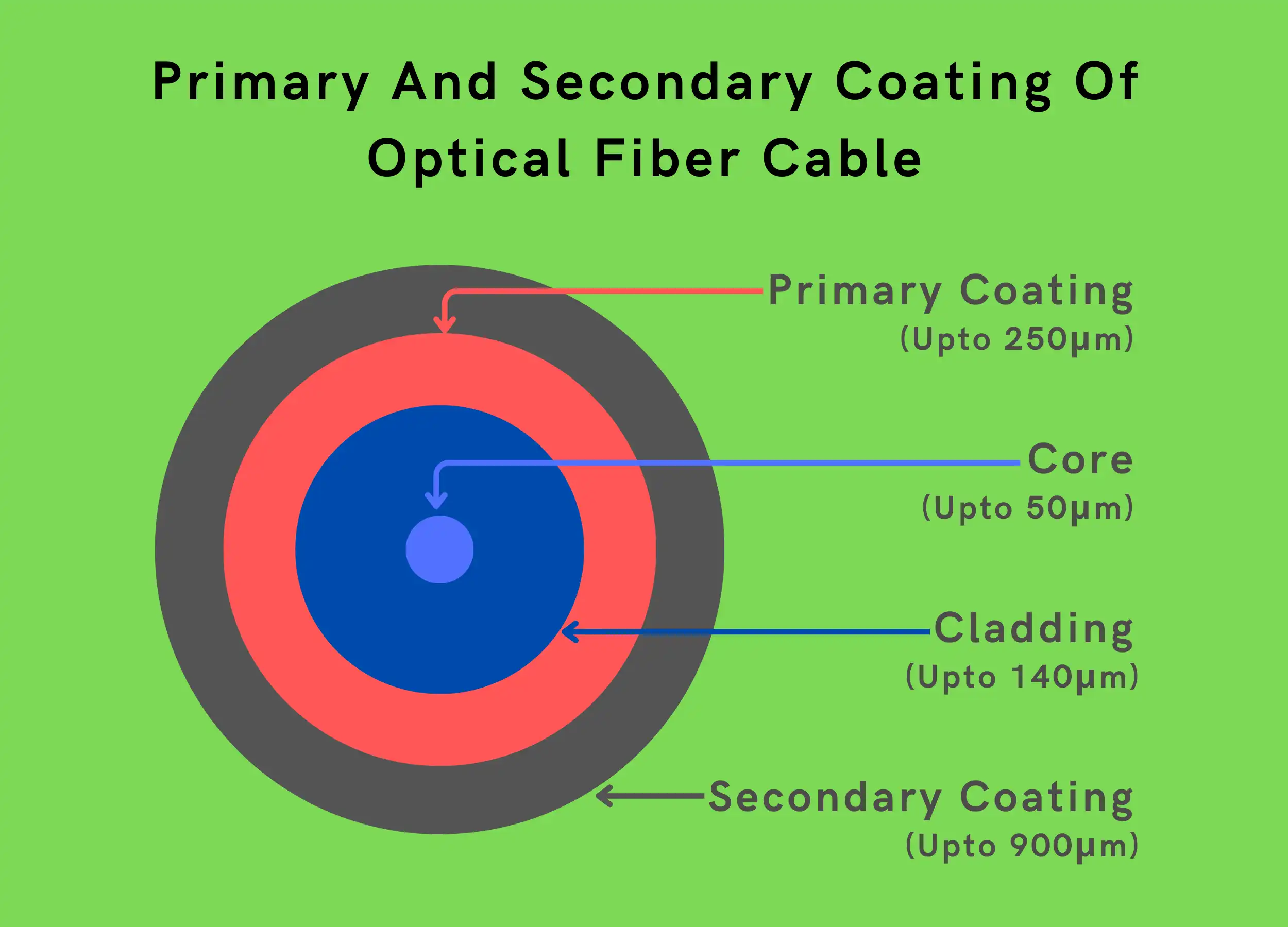
Diameter: Standard core diameters include 9 microns for single-mode and 50 to 62.5 microns for multi-mode fiber. Core size and refractive index differences affect data carrying capacity and distance reach.
Attenuation: Well-made glass cores transmit light with only 0.2 decibel loss per kilometer – allowing fiber runs of 50 kilometers or more. Plastic fibers have a higher attenuation of around 1 dB/km, limiting range.
Minimizing core impurities and defects during the complex manufacturing process is vital for achieving low signal loss through a fiber. Extreme precision when threading hair-thin cores through cable layers is also mandatory.
Cladding
The cladding layer surrounds the core and must have a lower refractive index to keep light signals inside the core. This refractive index differential creates total internal reflection for data transmission lengths up to 60 kilometers.
Material: Cladding glass contains high-purity silica dioxide like the core but with slightly lower concentration dopants to reduce refractive index.
Diameter: Cladding comes in standard sizes like 125 microns to support core diameters from 9 to 85 microns. A 140-micron cladding typically houses a 100-micron core.
Attenuation: Well-matched core and cladding attenuation coefficients ensure minimal signal loss at their interface. Cladding is custom-drawn during manufacturing to match cores.
Protection: The cladding protects the fragile fiber core from external mechanical stress and moisture. Precision control over cladding dimensions, surface smoothness, and concentricity is mandatory during the fiber draw process.
Coating
The primary and secondary coating layers help cushion the glass fiber from crushing forces and abrasion stresses. This protective barrier also blocks external moisture from degrading glass strength.
Primary Coating
The soft inner primary coating lies directly over the cladding glass to dampen external mechanical loads. It has a thickness of up to 250 microns and is made of acrylate or plastic.
Secondary Coating
The tough outer secondary buffer coating provides abrasion resistance from cabling operations or installations. It has a thickness of up to 900 microns and is typically made from acrylate polymers.
Identification: Color coding the secondary coating during manufacture facilitates identifying fiber strands in ribbon cables or loose tube designs. Common colors are blue, orange, and green.
Performance: Coating layers add no optical attenuation as long as their refractive index exceeds that of cladding glass. Proper curing during application and sufficient thickness ensures long service life.
Strength Member
Cable strength members bear pulling tension during installation and keep fibers intact if hanging or bending. Central strength rods also prevent buckling of loose tube or ribbon cables.
Loading: Strength reinforcements handle installation loads up to 600 pounds for backbone cables or 200 pounds for lateral pulls. Steel wires support the highest tensile loads.
Materials: Common strengtheners are fiberglass, aramid yarn, or steel – used individually or in combinations. The choice depends on flexibility, weight, corrosion resistance, and cost needs.
Fiberglass-Reinforced Plastic
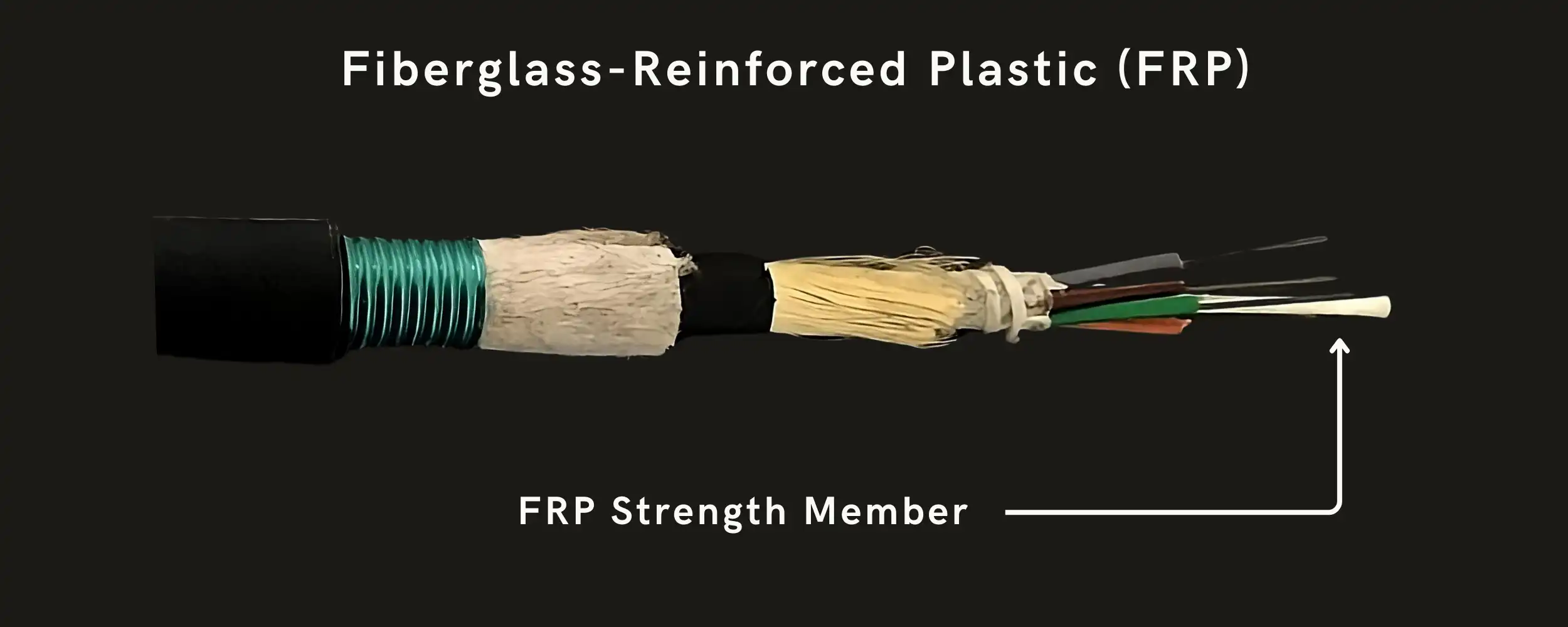
Fiberglass rods combine corrosion-proof glass reinforcement in an engineered plastic resin matrix. Pultrusion manufacturing aligns glass fibers for maximum tensile strength up to 10,000 psi.
Central Member: Fiberglass strength rods occupy the center void in high-count indoor/outdoor loose tube cables. This thermoplastic material is also cost-efficient for remote installations.
Fatigue Resistance: Fiberglass strengtheners have high fatigue resistance during cyclic cable loads along with thermal stability from -60° to +80° Celsius.
Aramid Yarn
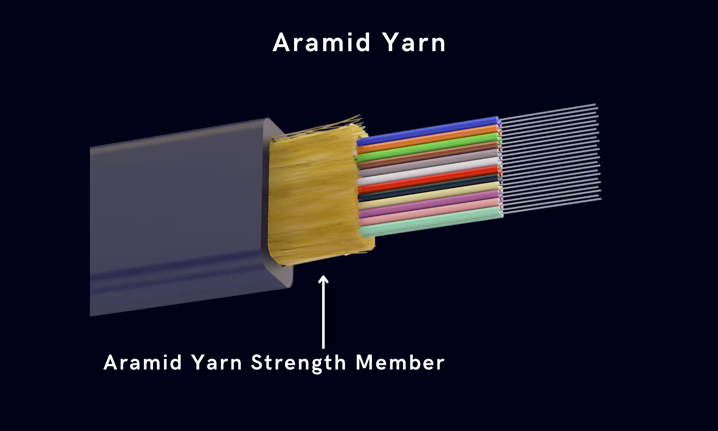
Aramid yarns (Kevlar®) provide exceptional tensile strength up to 400 Kpsi, along with a non-stretchability key for fiber protection. Aramid resists creep deformation from sustained loads better than fiberglass.
Lightweight: With a specific gravity of 1.44, aramid yarns add little weight despite having high strength. This helps combat cable sagging during long aerial spans.
Limiting Strain: Proper binding of aramid yarns ensures yarn breakage well before any fiber damage when overloaded. This prevents later cable failures from residual stretch or defects.
Steel Wire
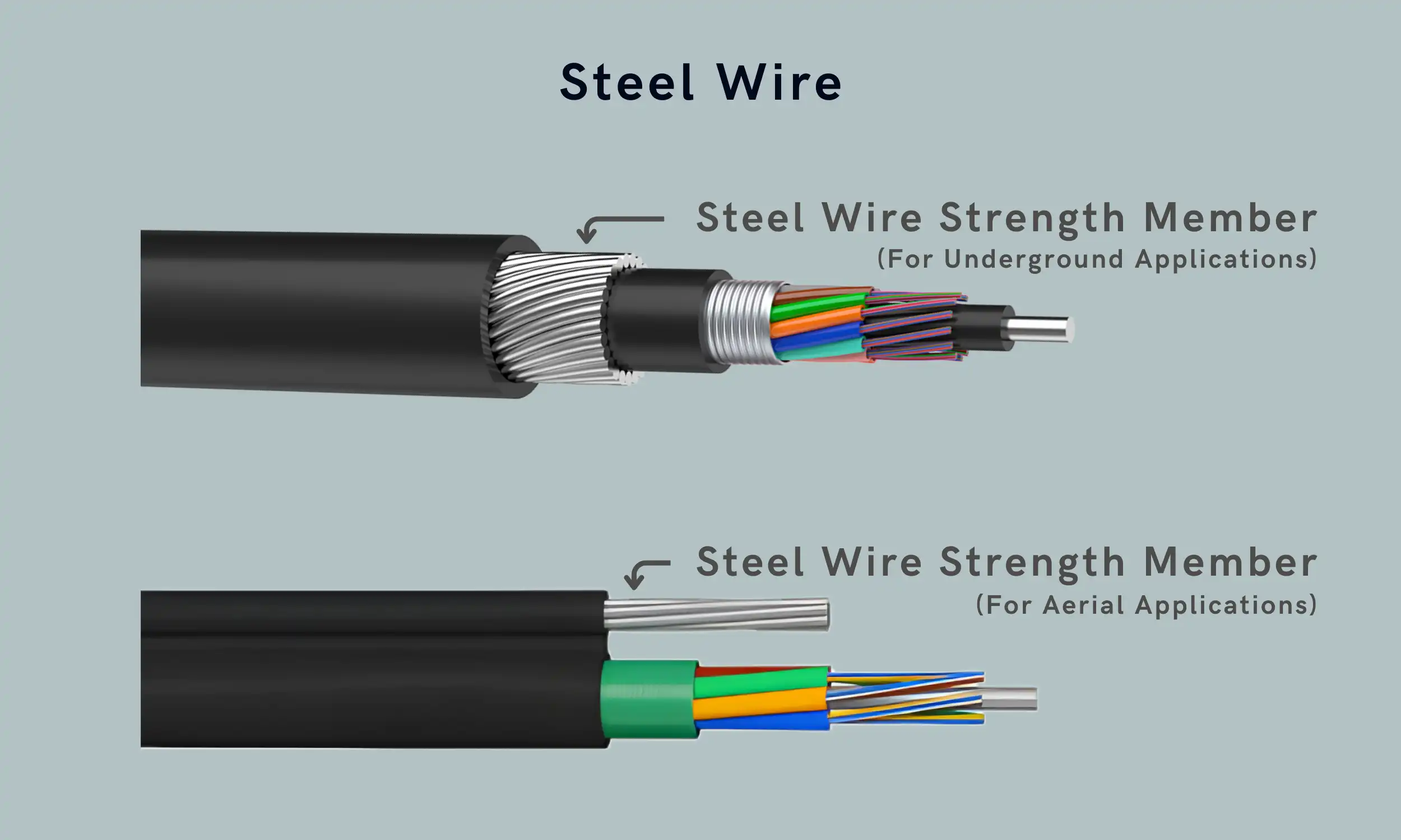
Galvanized steel wires offer the highest tensile strength exceeding 150 Kpsi, to support long cable runs. Wires are stranded for flexibility and to prevent corrosion in wet environments.
Fatigue Resilience: Steel strengtheners have very high fatigue strength during cyclic stresses along with creep resistance under persistent loading. This durability offsets the added weight.
Ubiquitous Use: Steel wires find use in almost every fiber optic cable type from indoor sub-units to backyard aerial drops to trans-ocean backbone systems. Concentrically stranded stainless steel is preferred for submarine cables.
Cable Jacket
The cable jacket provides the first line of defense against mechanical damage, moisture ingress, and other environmental threats that can degrade fiber performance. Cable jackets must withstand installation stresses plus years of environmental exposure.
Performance Requirements: Ideal jacket materials have wide operating temperatures, ultraviolet resilience, abrasion resistance, and high tensile/compression properties. Fire safety ratings are mandated for indoor cables.
Common Materials: Cable jackets employ thermoplastic or fluoropolymers depending on flexibility, cost, and installation needs. Polyethylene is popular for outdoor cables, while LSZH jackets meet fire codes.
Polyethylene (PE)
Polyethylene jackets provide an optimal balance of stiffness, environmental resistance, and cost-effectiveness. This has made PE the standard for outdoor fiber optic cables.
All-weather Protection: PE jackets have excellent moisture resistance backed by water absorption below 0.01%. They also handle temperature extremes from -50° to +80° C.
Durable: PE offers high tensile strength beyond 3000 psi, along with cut-through and abrasion resistance. PE jackets don’t crack from repeated bending or loading.
Polyvinyl Chloride (PVC)
PVC jackets have very good flame retardance and oil/chemical resistance and range from rigid to flexible formulations. Flexible PVC facilitates pulling through conduits while keeping costs low.
Indoor/Outdoor Use: Flexible PVC jackets reliably serve indoor and outdoor cables with impressive mechanical strength. This includes crush resistance beyond 220 psi for protection.
Limitations: PVC jackets tend to get stiff in cold weather. They also have poorer UV resistance versus polyethylene without sufficient additives.
Polyvinylidene Fluoride (PVDF)
PVDF fluoropolymer jackets meet stringent fire safety needs for indoor fiber cables while providing temperature versatility. PVDF produces extreme smoke density and toxic/corrosive gas when burned.
Superior Flame Retardance: PVDF jacket cables achieve the highest NEC safety rating of OFNP and NFPA 262 plenum approval. This allows routing through building air handling spaces.
Climate Resilience: PVDF jackets reliably serve indoor cables from -40° to +85°C. The material retains flexibility in low temperatures despite its firm composition.
Low Smoke Zero Halogen (LSZH)
LSZH jackets emit extremely low smoke and no toxic halogen gases when burned, meeting the fire code for crowded facilities. LSZH costs significantly more than traditional jacketing.
Public Safety: LSZH cables ensure tenability during fires – allowing safe egress through non-toxic fumes and better visibility from low smoke opacity. Jackets don’t fuel flame spread.
Global Compliance: LSZH jackets meet IEC 60332-3 flame standards as well as regulations across Europe, Asia, Australia, and North America for indoor usage.
Ripcord
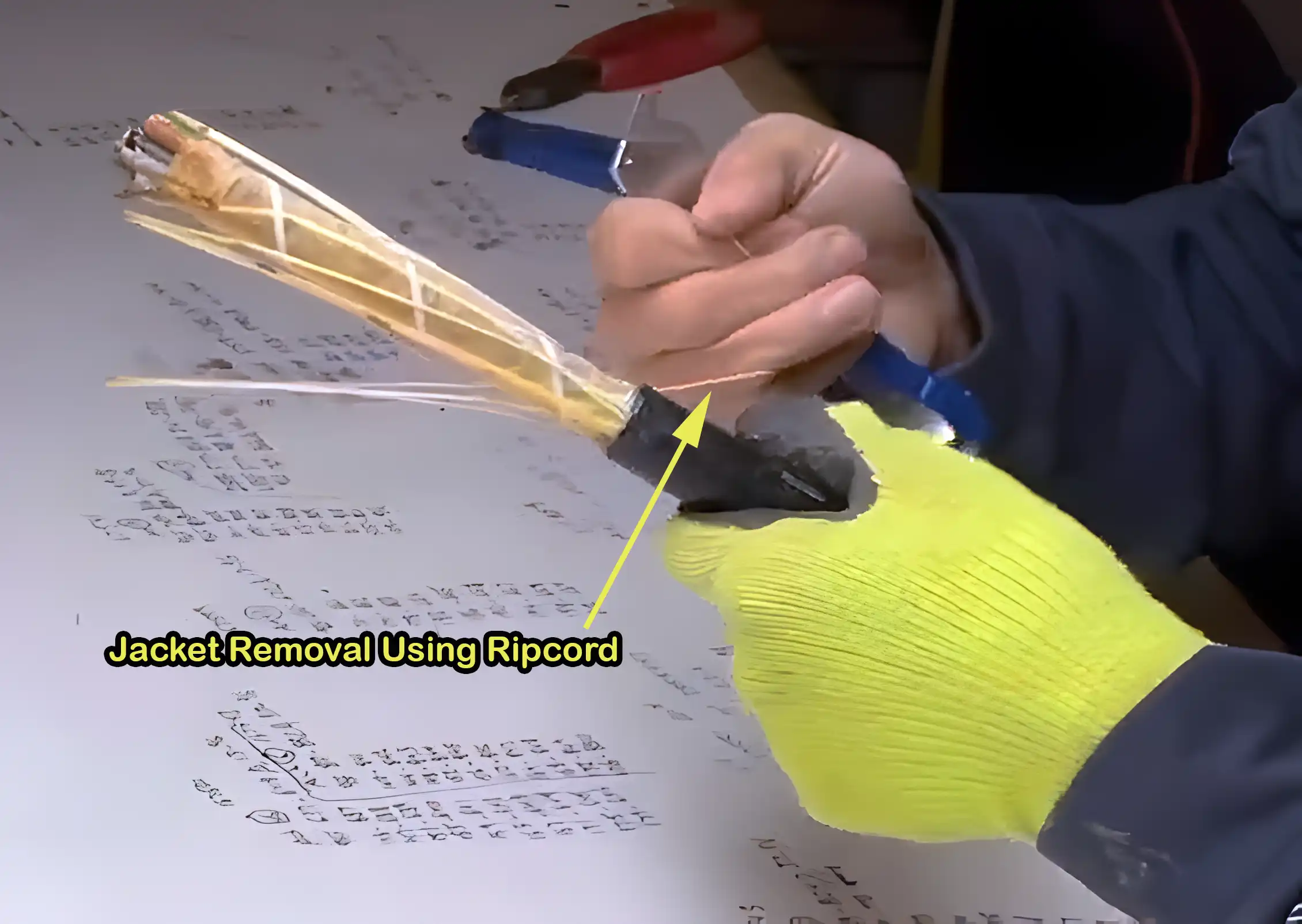
Ripcords are useful for quick, longitudinal jacket access when preparing fiber cables for termination or splicing. Nylon or polyester ripcords won’t snap when pulled and slice cleanly through cable jackets.
Material: Engineer-grade ripcords use high-tenacity yarns like Kevlar that rip easily through thick jackets without breaking. Other variants embed semi-conductive strands to locate the ripcord.
Installation Aid: Technicians grasp the ripcord with pliers and zip open cable jackets effortlessly despite cold weather or thick layers. Ripcords must slightly exceed the cable length.
Limitations: Ripcords don’t offer water protection through the slit jacket. The exposed interstices along the cord path can also allow moisture migration into the cable core if not resealed correctly.
Summary
Fiber optic cables are engineered composite structures fabricated to exacting standards for protecting tiny glass fibers that carry information using light. Matching specific cable components to operating conditions ensures optimal performance and service longevity when deploying fiber links.
The interdependent constituents like the strand coating, jacket, and strengtheners all play vital roles in mitigating risks from crushing, moisture, and tension. Advancements like LSZH jackets and ripcords further aid installation while upholding network capability.
Understanding cable construction allows for properly leveraging benefits from the various materials spanning core glass to the outer jacket. With cables accounting for up to 75% of network expenses, informed selection provides both technical and economic value for operators.
FAQ
What is the structure and working principle of optical fiber?
Optical fiber transmits light signals through total internal reflection within its layered structure. The core, cladding, and primary coating guide and protect the light as it travels, while additional layers in more complex cable designs provide further strength and environmental protection.
What are the two basic fiber optic cable structures?
The two primary types of fiber optic cable structures are Tight Buffered Cable and Loose Tube Cable. Tight Buffered Cables have a design where the fiber itself is coated with a protective layer, making it suitable for indoor applications. On the other hand, Loose Tube Cables contain multiple fibers encased in a tube filled with a water-resistant gel, making them ideal for outdoor use due to their better protection against environmental factors.
What are the three basic fiber optic cable designs?
The three basic designs of fiber optic cables are:
∎ Simplex, which contains a single fiber.
∎ Duplex, which contains two fibers for bidirectional data transfer.
∎ Multi-fiber, which contains several fibers in a single cable for complex network connections
What are the future trends in optical fiber cable design?
Advancements in materials and fabrication are leading to exciting developments:
∎ Microstructured fibers: With complex core designs for even lower dispersion and wider bandwidths.
∎ Hollow-core fibers: Guiding light through air instead of glass for potential ultra-low loss transmission.
∎ Integrated light sources and sensors: Fibers with inbuilt functionalities for various applications like medical imaging and environmental monitoring.
What are the 4 common fiber optic connectors?
The four common types of fiber optic connectors are:
∎ SC (Subscriber Connector or Standard Connector)
∎ LC (Lucent Connector)
∎ ST (Straight Tip)
∎ FC (Ferrule Connector)
These connectors are used to join optical fibers where a connect/disconnect capability is needed.


