Optical network system architecture provides a detailed overview of an optical communication system. It classifies all the network layers step-by-step in a logical form, describing each step in detail. From an architectural standpoint, fiber-optic communication systems can be classified into two broader categories:
- Point-to-Point (P2P): Connects two endpoints directly, offering high bandwidth and ideal for long-distance transmission.
- Point-to-Multipoint (P2MP): Splitters are used to distribute a single fiber optic signal to multiple users, and they are commonly used in FTTH deployments.
Table of Contents
Point-to-Point Architecture
Point-to-point links construct the simplest kind of optical communication systems. Their role is to transport digital bit streams from one place to another as accurately as possible. The link length can vary from less than a kilometer (short haul) to thousands of kilometers (long haul), depending on the application.
Initially, optoelectronic repeaters called regenerators were used to compensate for loss. A regenerator is a receiver-transmitter pair that detects the incoming optical signal, recovers the electrical bit stream, and then converts it back into optical form by modulating an optical source.
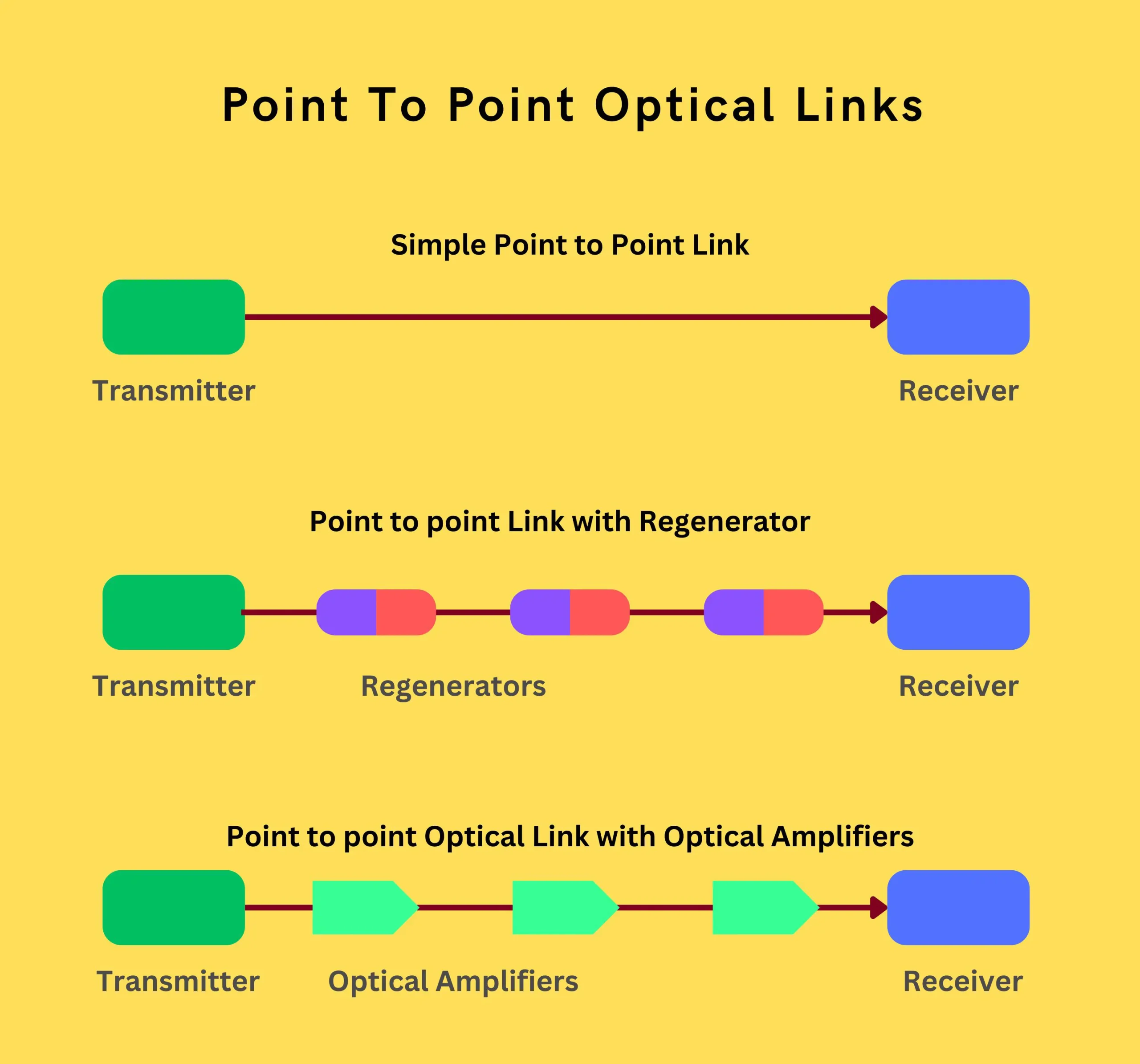
Around 1990, the advent of optical amplifiers revolutionized fiber-optic communication systems. Optical amplifiers amplify the optical bit stream directly without converting the signal to the electrical domain. They are valuable for WDM systems as they can amplify multiple channels simultaneously.
However, optical amplifiers add noise and worsen the impact of fiber dispersion and nonlinearity as signal degradation accumulates over multiple amplification stages. Optoelectronic repeaters do not suffer from this problem as they regenerate the original bit stream, effectively compensating for all sources of signal degradation.
Point-to-Multipoint Architecture
Many applications require information distribution to a group of subscribers, such as fiber-to-the-home (FTTH) networks, local loop telephone service distribution, and cable television (CATV video) broadcast. Transmission distances are relatively short (< 40 km), but the bit rate can be as high as 100 Gbps.
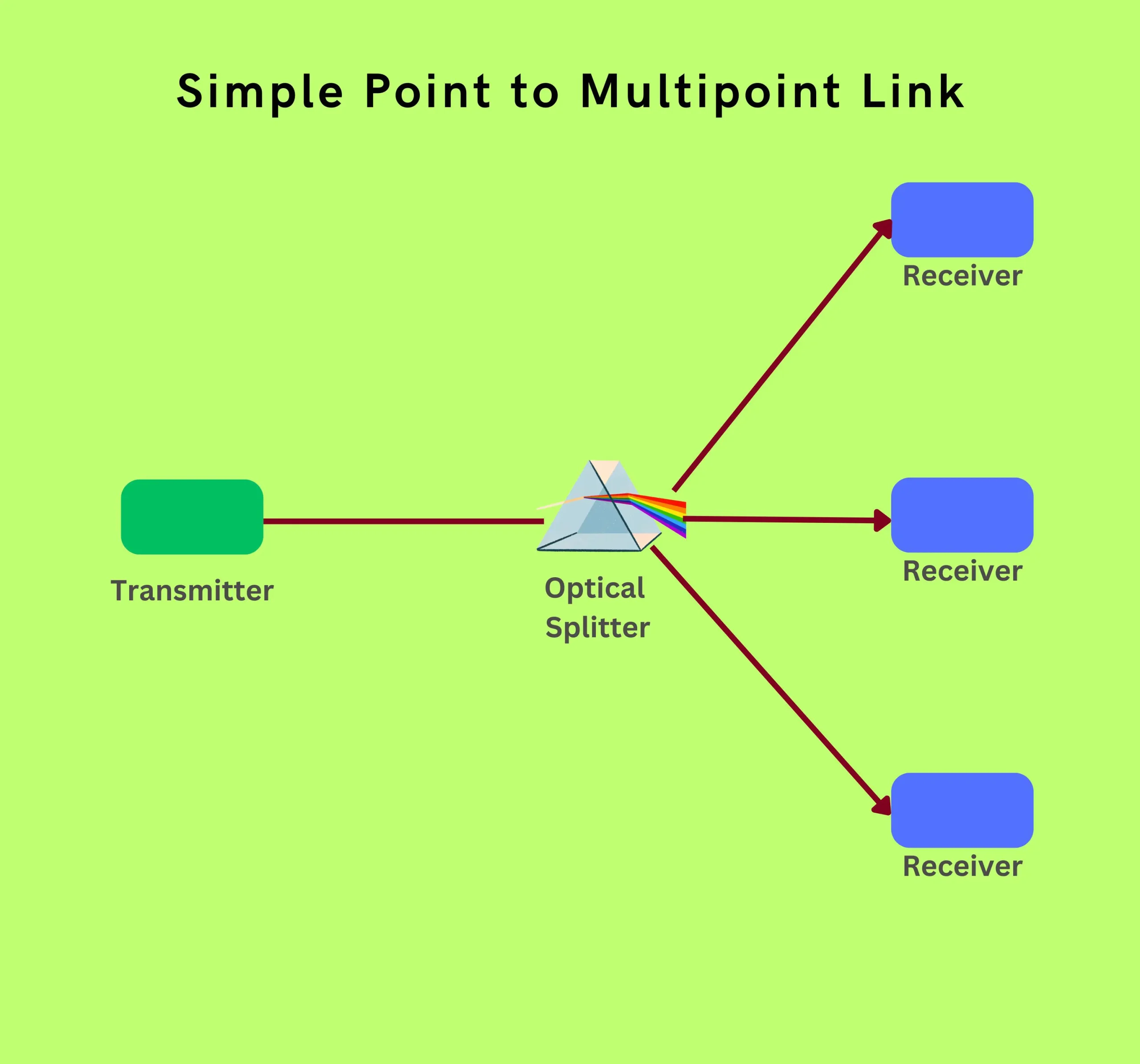
Point-to-multipoint networks are typically divided into three segments:
- Feeder network: Fiber network from the central office OLT to the first branching (1st level splitting) point.
- Distribution network: Fiber network from the first branching point to the curb connection point (or 2nd level splitting).
- Drop network: Fiber cable connecting the subscriber to the curb connection point and into the network.
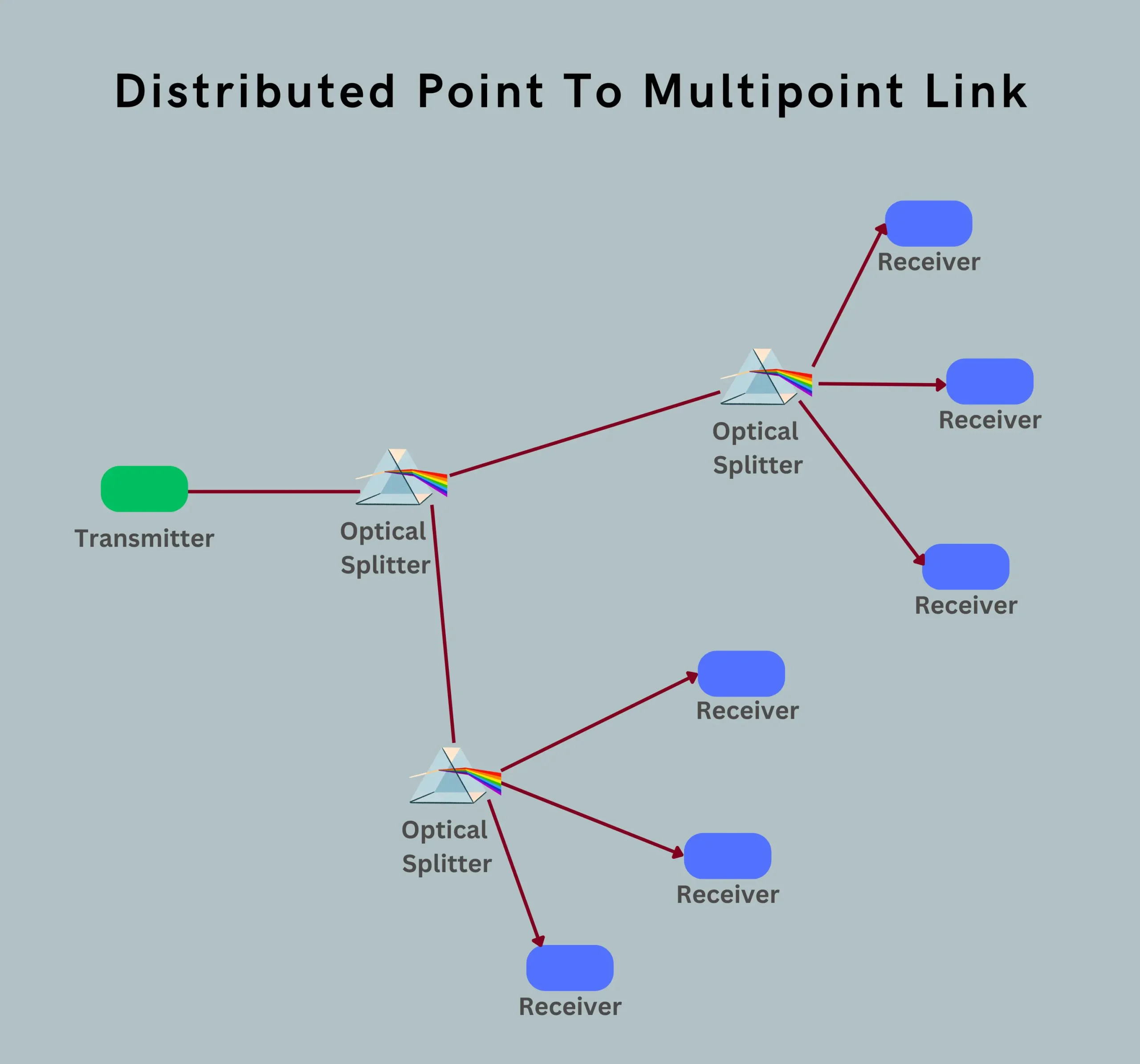
These architectures and their associated standards are fundamental in designing and deploying efficient and reliable fiber optic communication systems for various applications.
Fiber Optic Network Topology
The topology of a fiber optic network refers to how various nodes, devices, and links are physically or logically arranged in relation to each other. Six commonly used topologies are known:
- Ring topology
- Star topology
- Mesh topology
- Tree topology
- Bus topology
- Hybrid topology
Ring Topology
In the ring topology, consecutive nodes are connected by point-to-point links to form a closed ring. Each node can transmit and receive data using a transmitter-receiver pair, which also acts as a repeater.
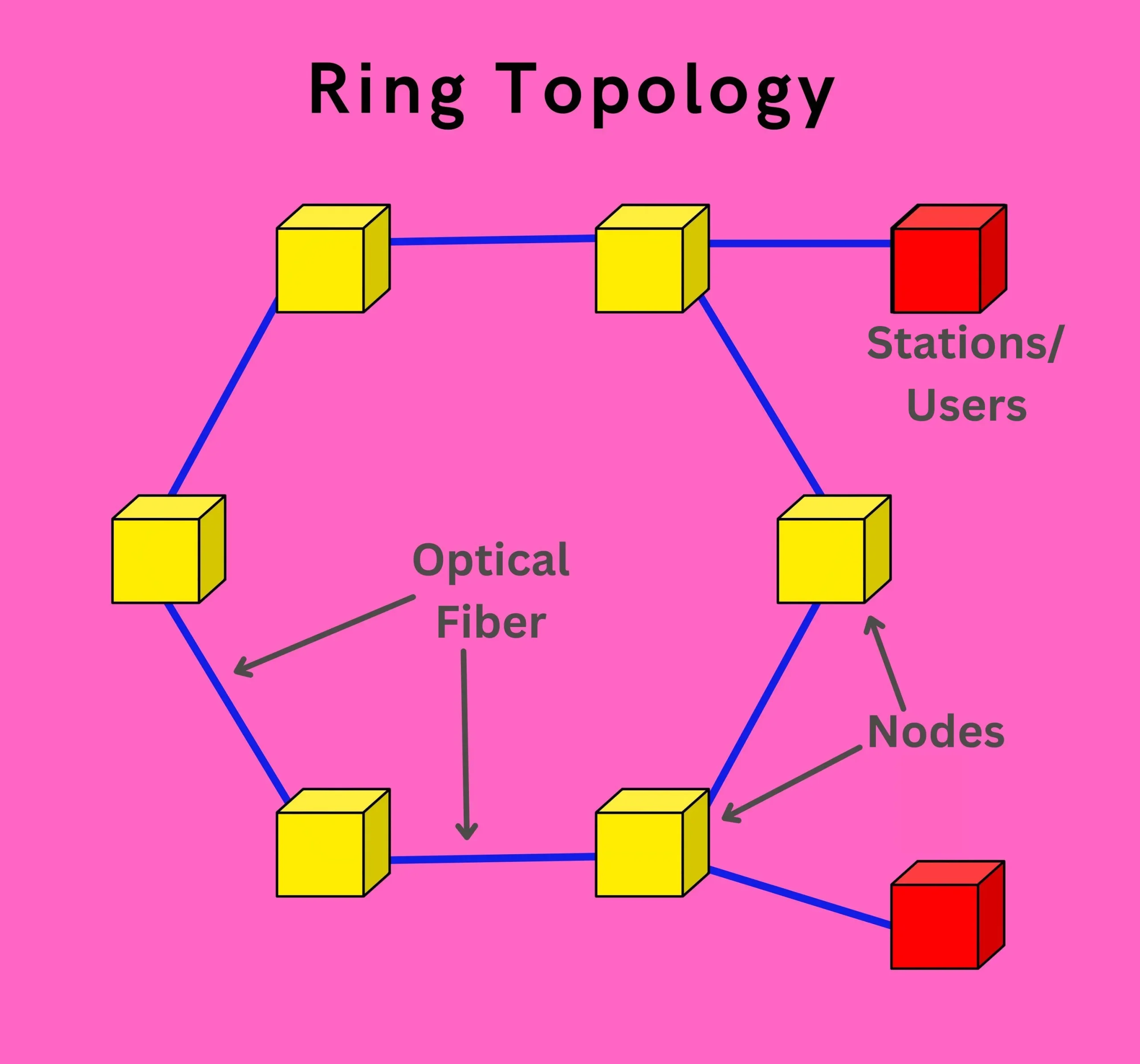
The ring topology offers simplicity and efficiency in data transmission. However, if one node fails, the entire network can be disrupted. To mitigate this risk, redundant rings or backup links are often implemented.
Some key points about the ring topology:
- Data flows in a unidirectional or bidirectional manner around the ring.
- Nodes act as repeaters, regenerating and forwarding the signal along the ring.
- Adding or removing nodes requires reconfiguration of the ring.
- Commonly used in metropolitan and wide-area networks for its capability to cover large geographical areas.
The ring topology’s simplicity, efficiency, and ability to span large distances make it a popular choice for fiber optic network deployments, especially in scenarios where redundancy and fault tolerance are critical requirements.
Star Topology
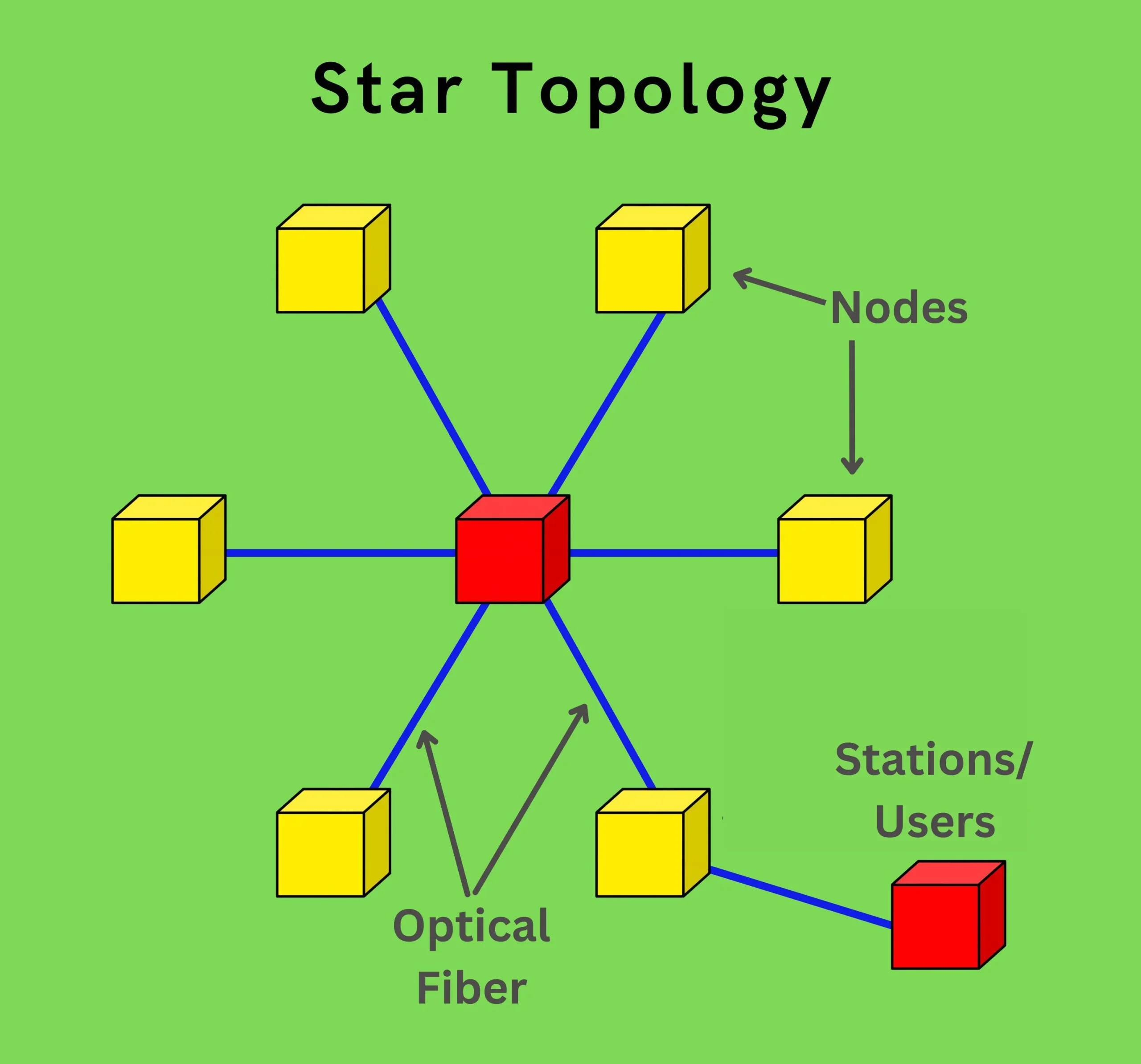
In the star topology, all nodes are connected through point-to-point links to a central node called a hub or star. Such topologies are further sub-classified as active-star or passive-star networks, depending on whether the central node is an active or passive device.
Active Star Topology
In an active star configuration, all incoming optical signals are converted to the electrical domain through optical receivers at the central node. The electrical signal is then distributed to drive individual node transmitters. Switching operations can also be performed at the central node since distribution takes place in the electrical domain.
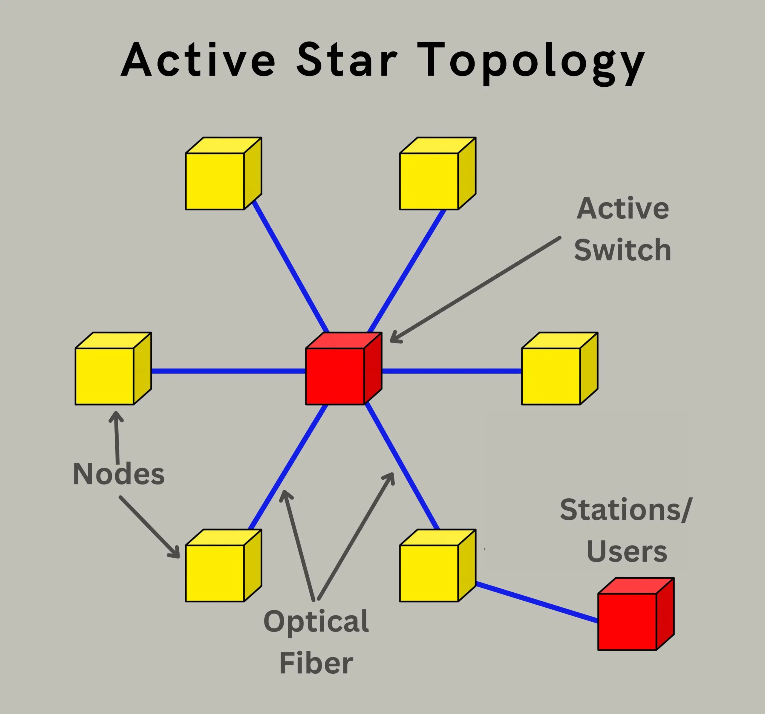
Key points about the active star topology:
- Requires active components (receivers, transmitters, switches) at the central node.
- Allows for signal regeneration, switching, and processing at the central hub.
- Offers centralized control and management of the network.
- Typically used in scenarios where signal processing or routing is required.
Passive Star Topology
In a passive star configuration, distribution takes place in the optical domain through devices such as directional couplers at the central node. The number of users supported by a passive-star topology is limited by distribution losses.
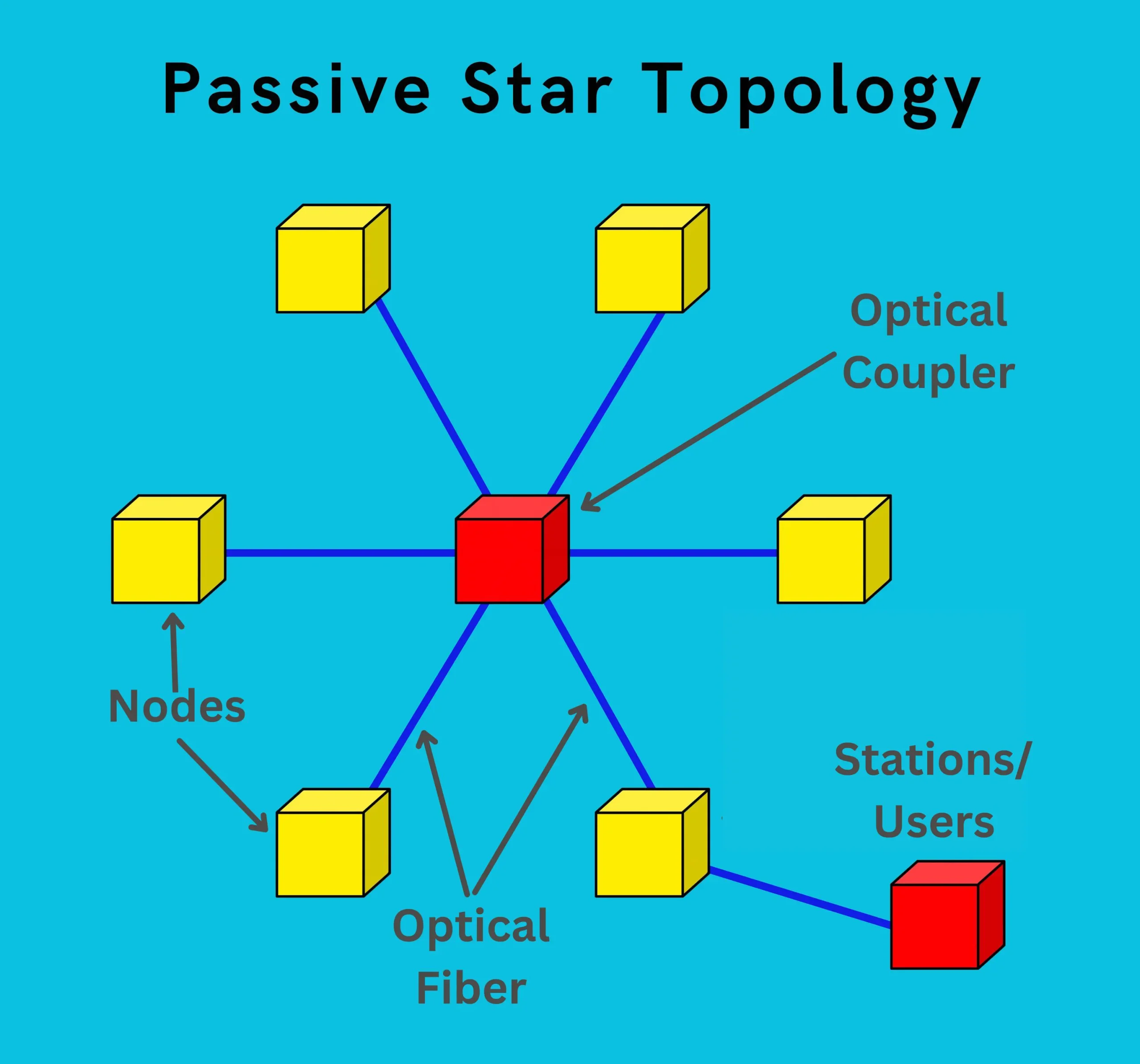
Key points about the passive star topology:
- Uses passive components (splitters, couplers) at the central node.
- No signal regeneration or processing at the central node.
- Simple and cost-effective implementation.
- Suitable for scenarios where signal distribution is the primary requirement.
- Number of supported users is limited due to power-splitting losses.
The choice between an active or passive star topology depends on factors such as the need for signal processing, network size, cost considerations, and specific application requirements.
Mesh Topology
In the mesh topology, an arbitrary connection is formed between all nodes in the network. This point-to-point connection can be changed according to the application. The flexible nature of the star topology means that in case of failure of one node, others can be used for signal transmission.
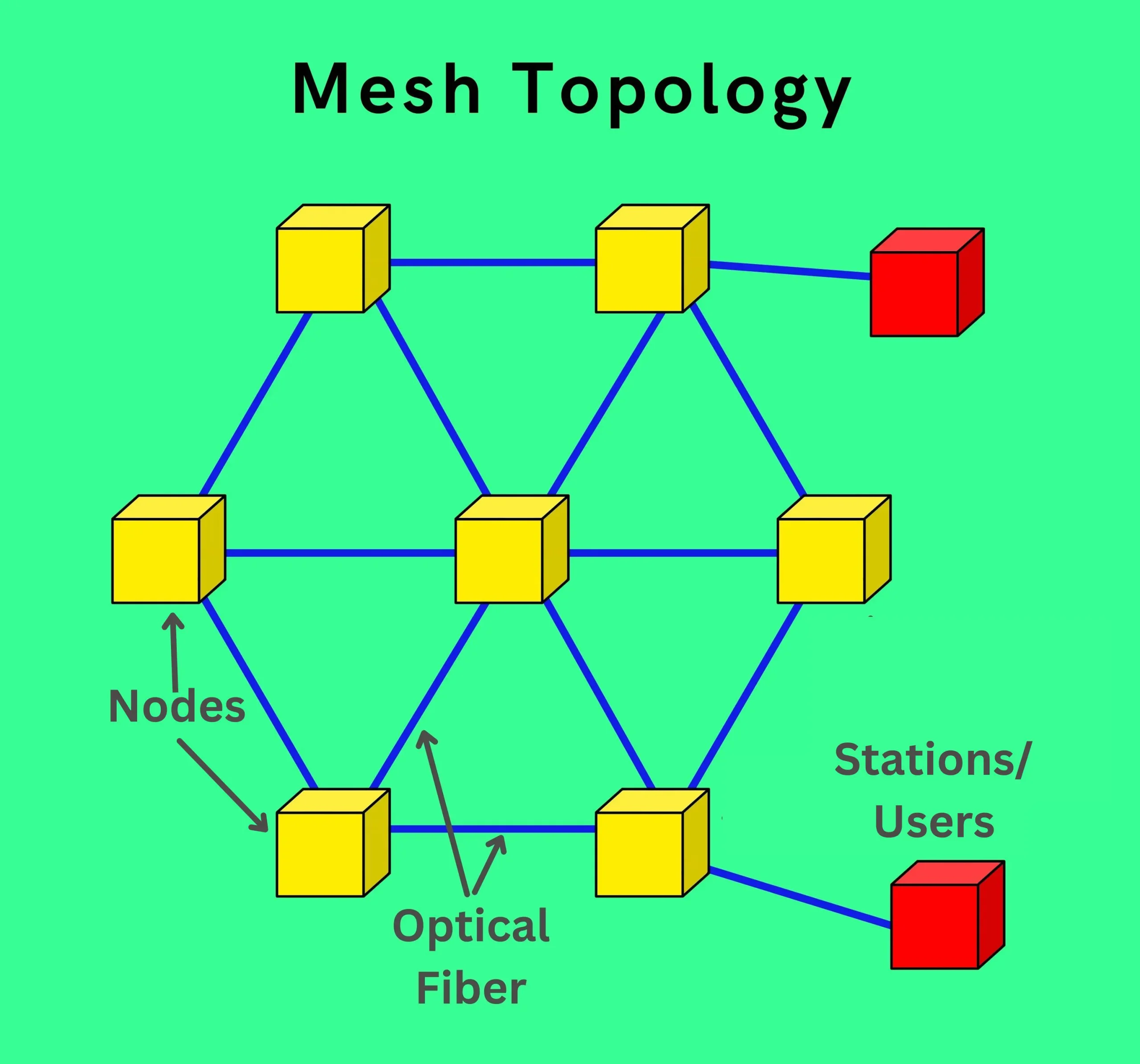
Key points about the mesh topology:
- Provides multiple redundant connections between nodes.
- Offers alternative paths for increased reliability and fault tolerance.
- Allows for reconfiguration and rerouting of connections based on application needs.
- Typically, it is more complex and expensive to implement compared to other topologies.
- Suitable for mission-critical applications that require high availability and redundancy.
The mesh topology’s redundancy and flexibility come at the cost of increased complexity and implementation costs, but it can be a valuable choice for applications that demand robust and adaptable network connectivity.
Tree Topology
In the tree topology, nodes are organized in the form of a tree, with a root node at the top of the hierarchical structure. A concern for the tree topology is related to its reliability – an outage of a single fiber cable can affect the service to a large portion of the network.
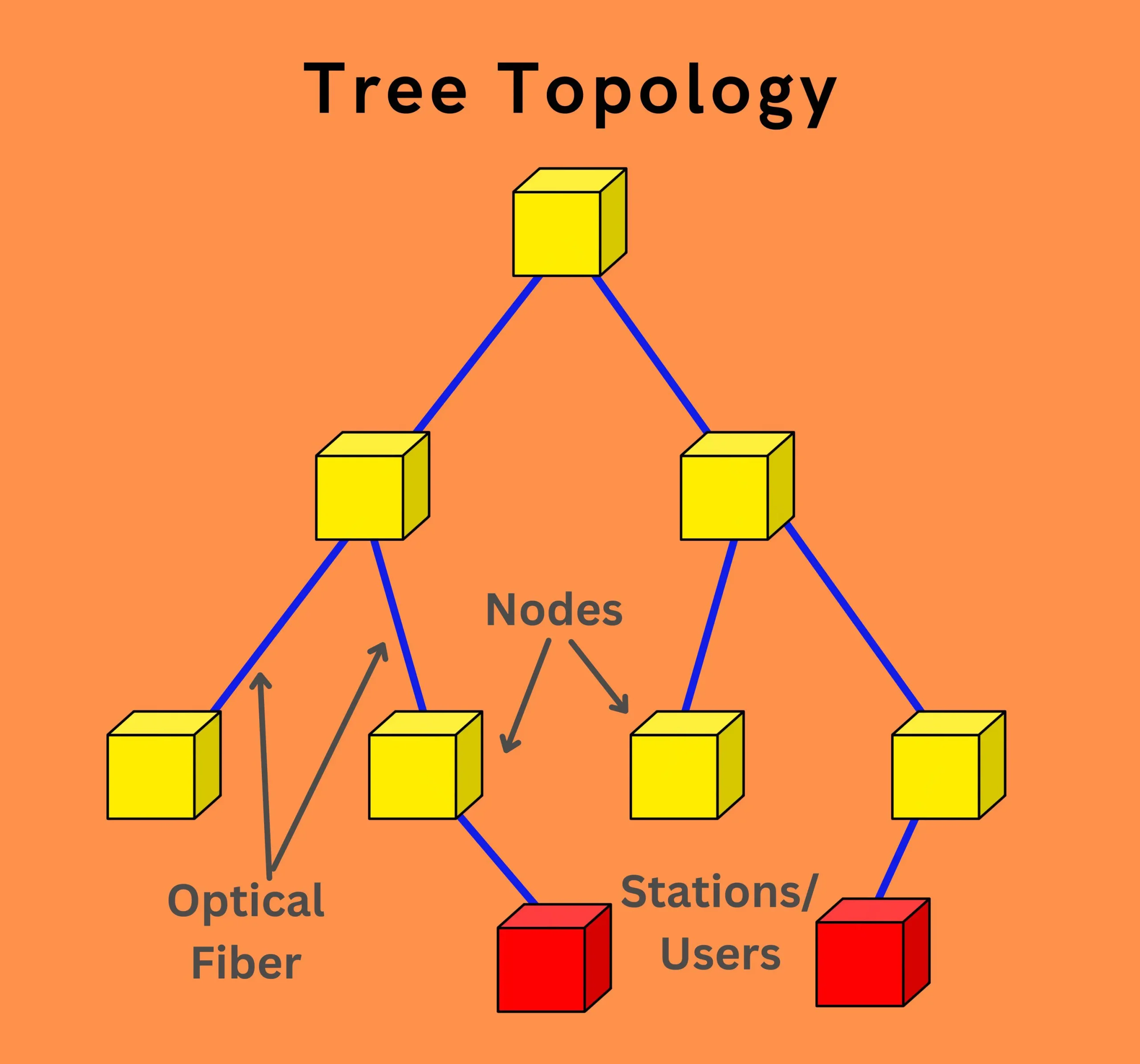
Key points about the tree topology:
- Hierarchical structure with a root node and multiple branches.
- Cost-effective and easy to implement for certain applications.
- Scalable by adding more branches or sub-trees.
- Vulnerable to single points of failure, as a cable outage can disrupt service to a large portion of the network.
- Additional point-to-point links can be used to guard against such outages by connecting important node locations directly.
While the tree topology offers simplicity and scalability, its vulnerability to single points of failure can be a significant drawback. Implementing redundant links or alternative paths can help mitigate this issue but at the cost of increased complexity and deployment costs.
Bus Topology
In the bus topology, a single fiber cable carries the multi-channel optical signal throughout the area of service. Distribution is done by using optical taps or optical couplers, which divert a small fraction of the optical power to each subscriber.
A major issue with the bus topology is that the signal loss increases exponentially with the number of taps, limiting the number of subscribers served by a single optical bus.
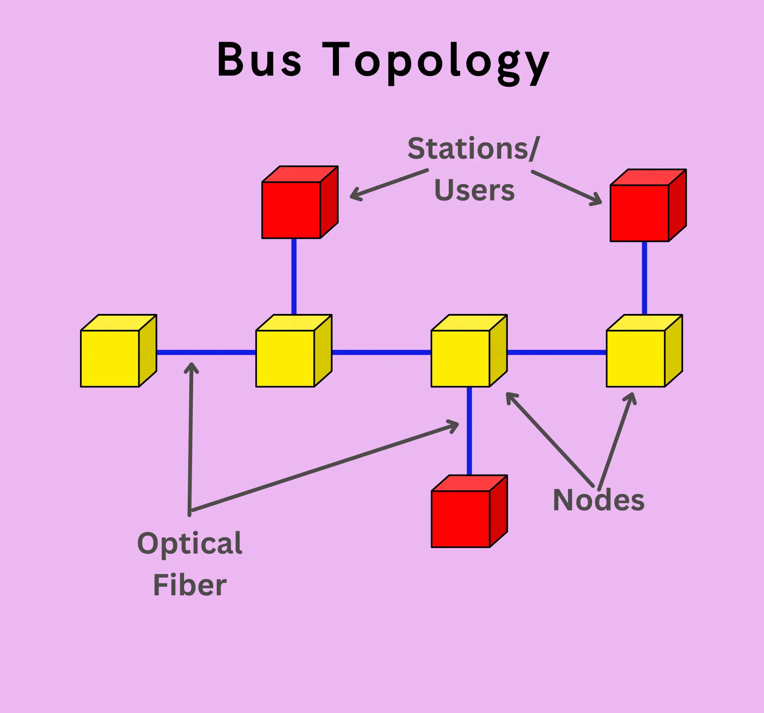
Key points about the bus topology:
- Simple and cost-effective for specific applications.
- Suitable for scenarios where distribution of a common signal to multiple subscribers is required.
- Signal loss increases as more taps are added, limiting the scalability and reach of the network.
- Failure of the main fiber cable can disrupt service to the entire network.
- Typically used in local or campus-wide applications with limited geographical coverage.
While the bus topology offers simplicity and cost-effectiveness, its limitations in terms of signal loss, scalability, and fault tolerance make it less suitable for larger or more complex fiber optic network deployments.
Hybrid Topology
A hybrid topology is a combination of different network topologies. The commonly used combinations are:
- Star-bus network: Consists of two or more star topologies connected using a bus trunk.
- Star-tree topology: Can be viewed as a collection of star networks arranged in a hierarchical structure.
Key points about hybrid topologies:
- Combines the advantages of different topologies to suit specific application requirements.
- Can provide a balance between cost, performance, scalability, and fault tolerance.
- Allows for more complex and customized network designs.
- Increased complexity in implementation and management compared to single topologies.
Hybrid topologies offer flexibility and customization by combining the strengths of different topologies, but they also introduce increased complexity in design, implementation, and management.
Conclusion
We provided an overview of the key characteristics of fiber optic communication system architectures and common fiber optic network topologies. The ring, star, mesh, tree, and bus topologies each have advantages and limitations depending on the application requirements.
The ring topology offers simplicity and efficiency over long distances but has a single point of failure risks. The star topology allows for centralized control but has limitations based on whether it uses active or passive components.
The mesh topology provides high reliability through redundant links but at increased complexity. Hybrid topologies combine the strengths of different single topologies but also introduce more complexity.
Overall, selecting the optimal topology requires understanding specific needs for performance, scalability, fault tolerance, and costs in order to design efficient and reliable fiber optic networks.
Going forward, network designs will likely incorporate aspects of different topologies alongside new technological advancements to best serve evolving connectivity demands.
FAQ
What are the three parts of a fiber optic communication system?
A basic fiber optic communication system consists of three main parts:
➤ Transmitter: Converts electrical signals into light pulses. (e.g., Laser diode)
➤ Transmission medium: The optical fiber cable that carries the light pulses.
➤ Receiver: Converts the received light pulses back into electrical signals. (e.g., Photodiode)
What are the basics of fiber optic communication?
Fiber optic communication transmits data using light pulses instead of electrical signals. Light travels through the fiber optic cable with minimal signal degradation, enabling high bandwidth and long-distance transmission compared to copper cables.
How are fiber optic networks constructed?
Fiber optic networks involve laying down fiber optic cables underground or overhead. Techniques like trenching, directional boring, and aerial deployment are used depending on the environment. Specialized equipment splices the fibers together to create a continuous network.
What does FTTH stand for?
FTTH stands for Fiber-To-The-Home. It’s a technology that delivers internet and voice services directly to a home using fiber optic cables.
What is the basic architecture of the FTTH (Fiber-To-The-Home)?
FTTH architecture typically involves three segments:
➤ Feeder network: This fiber optic cable runs from the service provider’s central office to the first branching point in the network.
➤ Distribution network: This section carries the signal from the branching point to the neighborhood connection point.
➤ Drop cable: This is the individual fiber connecting a subscriber’s home to the network.
Within this architecture, Point-to-Multipoint (P2MP) designs are common, using passive optical splitters to distribute the signal to multiple homes from a single fiber.


