Optical fibers are thin glass rods that use the properties of light reflection and refraction to transmit data over long distances. They actively shuttle data encoded in pulsing light across vast distances using only subtle differences in materials. Light undergoes total custody within its cores through cunningly engineered refractions and reflections. Understanding concepts like refractive index, critical angle, and total internal reflection is key to knowing how fiber optics work.
This article will give you an overview of these topics and how they enable fiber optic communication.
Table of Contents
Refraction vs Reflection
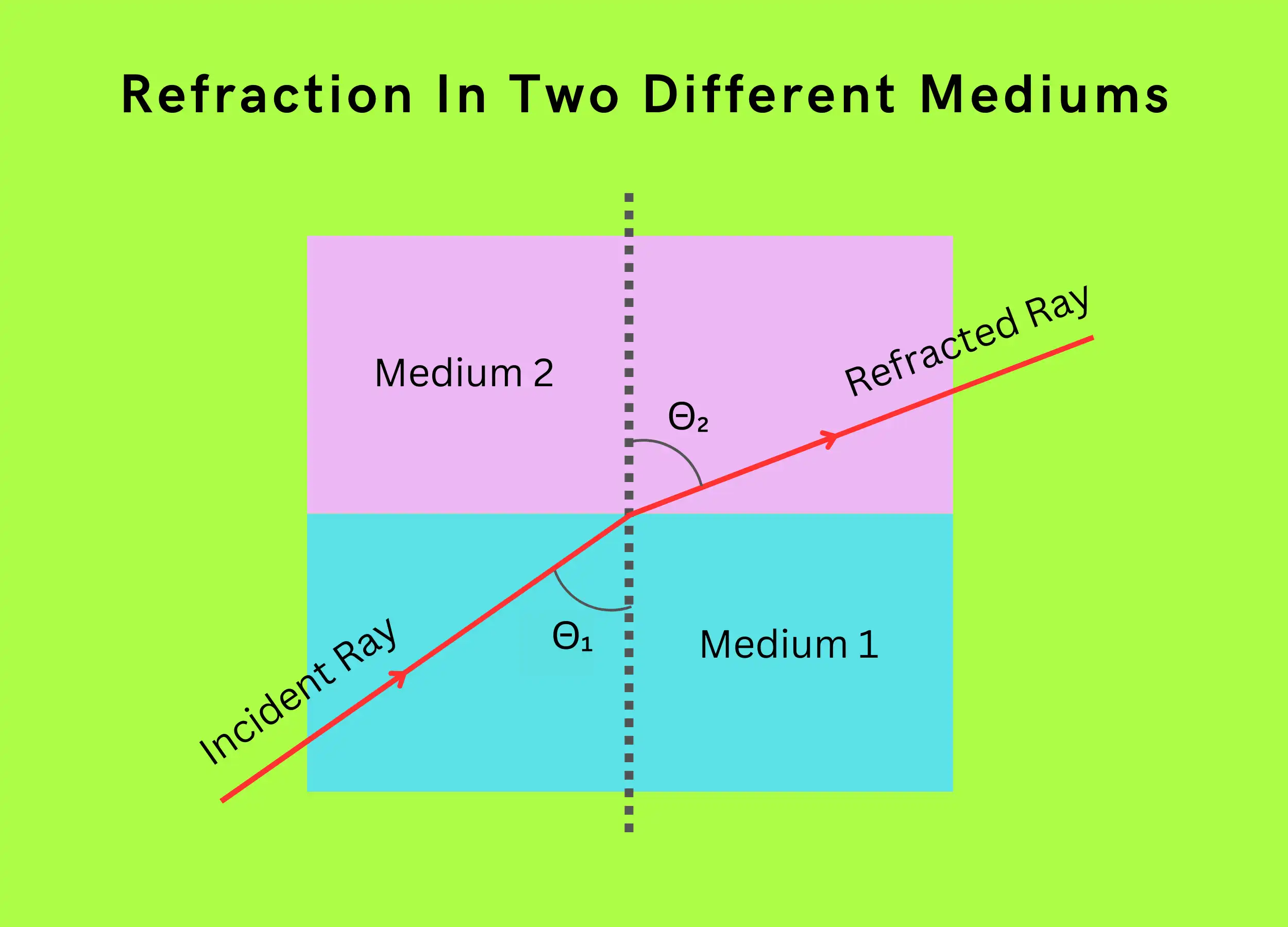
Refraction is when a ray of light bends as it passes between two transparent materials like air and glass. The degree of bending depends on the materials’ refractive indices.
Reflection is when light bounces off a smooth surface like a mirror and returns to the original medium. Reflection can be specular, where the angle of incidence equals the angle of reflection or diffuse.
Refraction and reflection behave differently at material boundaries:
- Refracted light changes speed and direction. Reflected light only changes direction.
- The angle of refraction depends on the two materials’ refractive indices. The angle of reflection equals the angle of incidence.
How is Refraction Different from Reflection?
Refraction and reflection both involve light interacting with material interfaces. But there are some key differences:
- Refraction is like a car changing lanes – the light shifts in direction as it enters the new medium.
- Examples are lenses, prisms, and your finger looking bent in water. Light bends at the material boundary.
- Reflection is like a ball bouncing off the ground – the light returns to the original medium at the same angle it struck the surface.
- Examples are mirrors, polished metal, and water surfaces. Light bounces off smoothly.
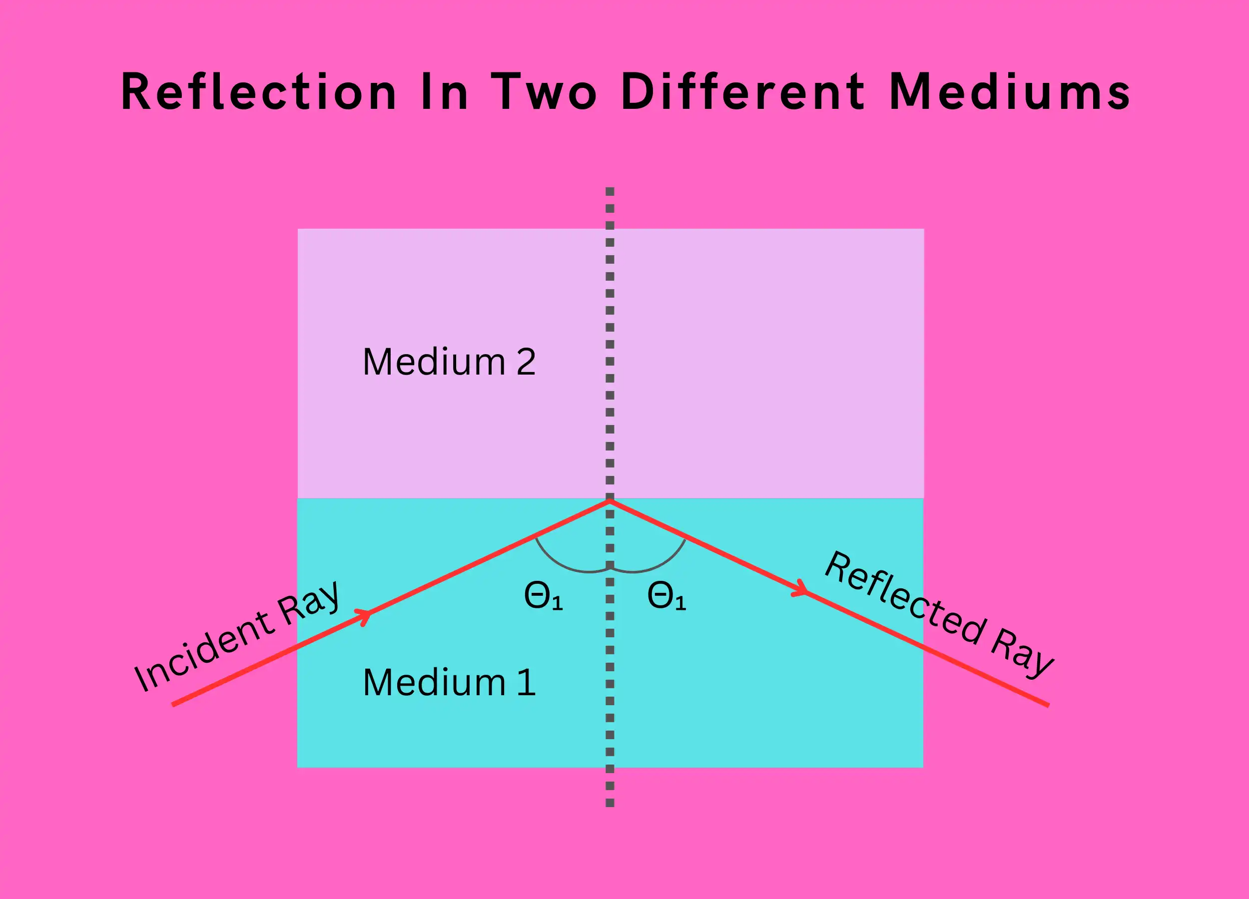
- Reflection doesn’t change light speed. Refraction slows light down as it transfers between materials.
- The refractive index ratio between materials determines the refraction angle via Snell’s law. Reflection angle equals incidence angle.
So, in summary:
- Reflection: Light bounces off surfaces and maintains speed. The angle in = the angle out.
- Refraction: Light bends when entering a new material and slows down. The angle changes depending on the materials’ refractive indices.
Refractive Index
An important optical parameter of a medium is its refractive index. When a light wave enters a dielectric or non-conducting medium, it slows down to a new speed s. The speed of light in a vacuum is c.
- The ratio of c to s is the refractive index (n) of the medium.
- If two mediums are involved in light transmission, the one with the larger n value is optically denser.
The refractive index (n) is a fundamental optical property of a material. It measures how much the material slows down light passing through it.
The refractive index is calculated as:
\( n=\frac{Speed\;of\;Light\;in\;Vacuum}{Speed\;of\;Light\;in\;Material}\)
So, in air, n ≈ 1. In glass, n is around 1.5.
A higher n means light travels slower in that material. This also causes more bending at material boundaries.
Some common refractive indices:
- Air – 1.000293
- Water – 1.33
- Silica glass – 1.45
- Crown glass – 1.52
- Diamond – 2.42
You can calculate the Refractive Index using our calculator here.
Refractive Index of Core and Cladding in Optical Fiber
Optical fibers have a glass core surrounded by plastic cladding. The core has a slightly higher refractive index:
- Core n: 1.46 to 1.55
- Cladding n: 1.45
This small difference, usually around 1%, is enough to cause total internal reflection and guide light along the fiber.
Here are examples of core and cladding refractive index differences:
- Silica core fiber:
- Core n = 1.50
- Cladding n = 1.47
- Silicone core multimode fiber:
- Core n = 1.460
- Cladding n = 1.455
The specific indices depend on factors like material composition and manufacturing process. However maintaining an n contrast between core and cladding is essential for fiber optics.
Why Cladding Has a Lower Refractive Index Than Core
The cladding’s lower refractive index is crucial to trapping light in the core through total internal reflection:
- Light moves slower in the higher index core. At the boundary, light rays bend towards the normal line.
- If the cladding index equaled the core, the light would pass straight from the core to the cladding and leak out.
- A lower cladding index causes light to refract at sharper angles. Above a certain critical angle, it reflects back into the core.
- This total internal reflection at the boundary confines light to the core as it travels down the fiber.
So, the lower cladding index enables total internal reflection, which is essential to fiber optic transmission.
The Law of Refraction
The law of refraction describes what happens when light passes from one transparent material to another at an angle. It is also called Snell’s Law.
- When light moves from one material to another, it changes direction. This is called refraction.
- The amount of bending depends on the refractive index of each material.
- The refractive index measures how much light slows down in a material.
The law of refraction says:
- The light ray, the refracted ray, and the line perpendicular (normal) to the surface all lie in the same plane.
- There is a constant ratio between the sines of the angle of incidence (Θ₁) and the angle of refraction (Θ₂).
- This can be written as the equation:
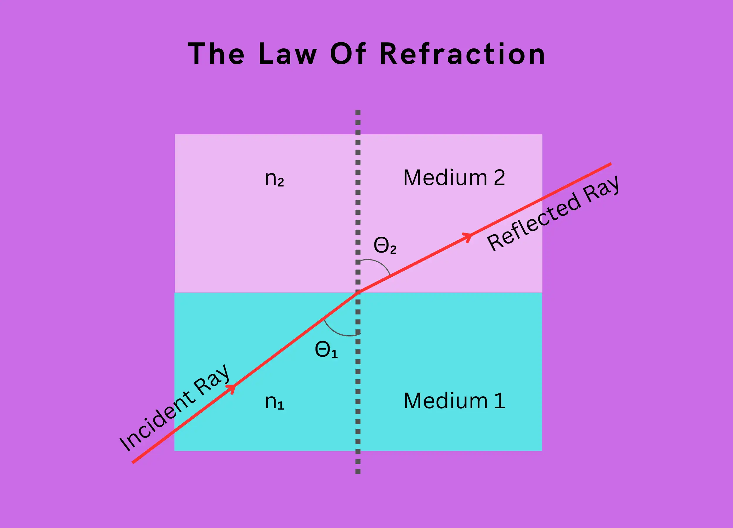
\(n_1sin(\Theta_1)=n_2sin(\Theta_2)\)
Where:
- n₁ is the refractive index of material 1
- n₂ is the refractive index of material 2
- Θ₁ is the incident angle
- Θ₂ is the refracted angle
So in simple terms, the law describes how light bends between materials depending on their refractive indices. The angles and refractive indices are connected by a constant ratio.
Critical Angle
The critical angle (Θ꜀) is the angle of incidence where the refracted light skims along the surface between two materials. At this angle, the refracted light ray is bent to 90 degrees.
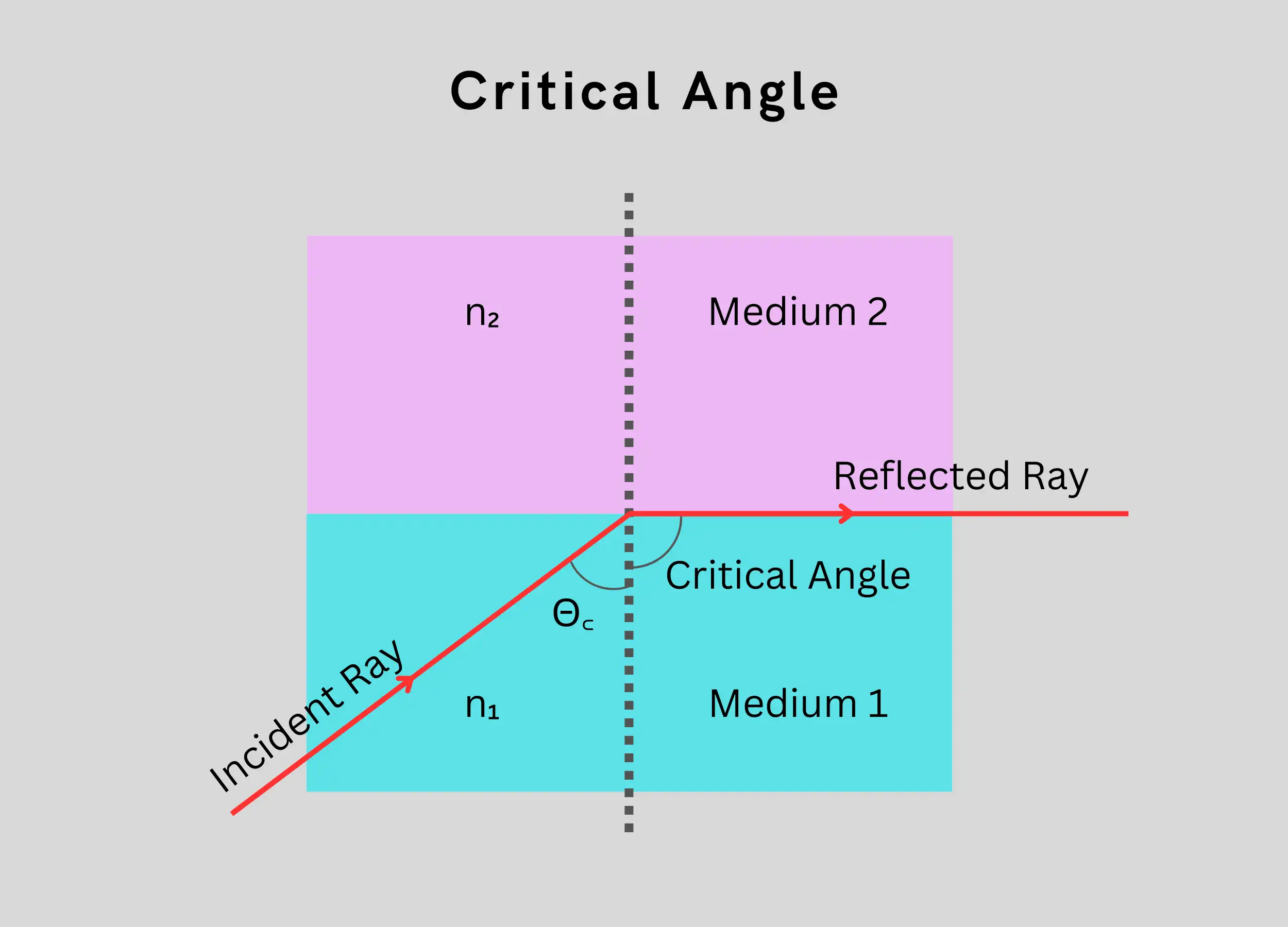
- When the incident angle equals the critical angle (Θ꜀), the refracted light is bent to 90 degrees.
- To calculate the critical angle:
- Use Snell’s law: n₁ * sin(Θ₁) = n₂ * sin(Θ₂)
- Set Θ₂ to 90 degrees since the refracted ray is bent to 90°.
- Solve to find the angle Θ₁, which is the critical angle Θ꜀.
For example, say light is moving from glass (n₁ = 1.5) to air (n₂ = 1):
- n₁ * sin(Θ₁) = n₂ * sin(90)
- 1.5 * sin(Θ₁) = 1 * sin(90)
- sin(Θ₁) = 1/1.5 = 0.667
- Θ1 = sin-1(0.667) = 41.8 degrees
So the critical angle at a glass-air surface is 41.8 degrees.
In summary:
- The critical angle is where the refracted light is bent to 90°
- Use Snell’s law and set Θ₂ to 90° to calculate Θ꜀.
- This is the maximum angle light can strike the surface and still refract into the second material.
Critical Angle in Optical Fiber
- In optical fibers, Θ꜀ is typically around 82°.
- This is because the core index is usually only 1% higher than the cladding.
- Light reflects back into the core for incidence angles > 82°, confining transmission through the fiber.
- A larger core-cladding index difference would decrease Θ꜀, increasing the range of confined propagation angles.
Difference Between Acceptance Angle and Critical Angle
- The acceptance angle is measured from outside the fiber. This is the maximum angle at which incoming light is transmitted down the fiber.
- The critical angle is measured within the fiber at the core-cladding boundary. It defines the onset of total internal reflection.
- A larger core-cladding refractive index difference increases the acceptance angle but decreases the critical angle.
So, in summary:
- Acceptance angle: Maximum external angle for transmission.
- Critical angle: Internal angle threshold for total internal reflection.
Total Internal Reflection
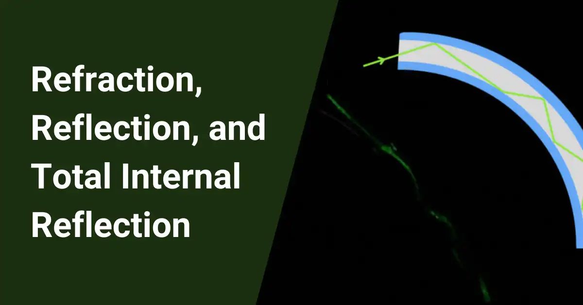
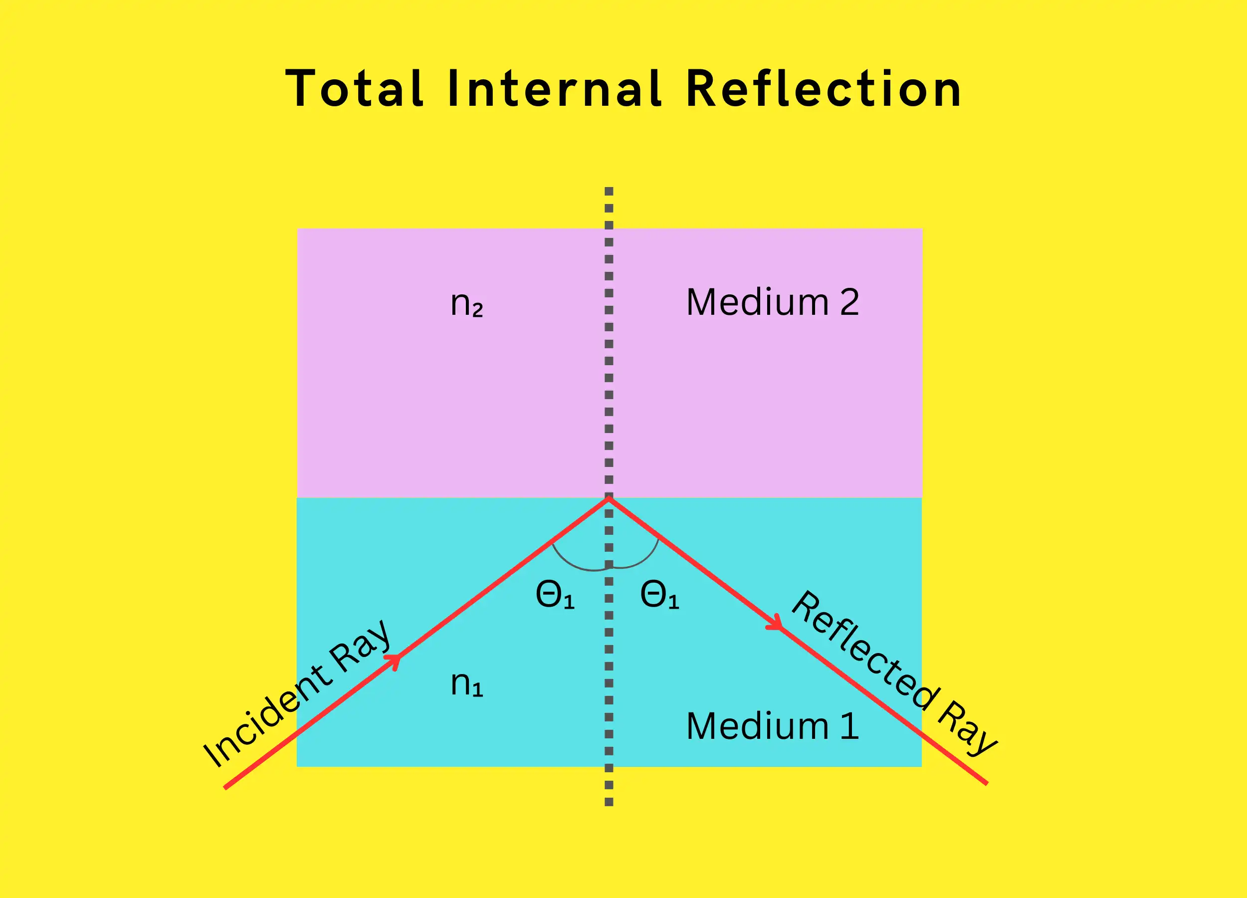
Total internal reflection (TIR) occurs when light strikes a less optically dense material above the critical angle. This causes 100% of the light to reflect back into the denser medium.
TIR requires:
- Light moves from a higher → lower refractive index
- Incident angle > critical angle
When both conditions are met, TIR confines the light to the denser medium rather than transmitting across the boundary.
The Formula of Total Internal Reflection
The formula describing total internal reflection is:
\(n_1sin(\Theta_1)>n_2sin(\Theta_2)\)
Where:
- n₁ = refractive index of initial medium
- n₂ = refractive index of the second medium
- Θ₁ = angle of incidence
- Θ₂ = angle of refraction
When this relationship holds, TIR occurs rather than refraction.
Conditions for Total Internal Reflection
Total internal reflection requires:
- Optical density mismatch – light passing from a medium of higher refractive index to a lower one.
- Incidence angle exceeding critical angle – light hitting the interface at an angle beyond the threshold for refraction.
When light moves from a high to low index medium above the critical angle, TIR causes complete reflection back into the original dense medium.
Total Internal Reflection in Optical Fiber
Total internal reflection is the key to how optical fibers work to transmit information using light.
- Optical fibers have a glass core surrounded by a cladding layer.
- The core has a higher refractive index than the cladding.
When light in the core hits the boundary with the cladding:
- If the angle is small, the light passes through into the cladding and gets lost.
- If the angle is very large (beyond the critical angle), the light reflects back into the core instead of refracting.
- This total internal reflection traps the light inside the core as it travels down the fiber.
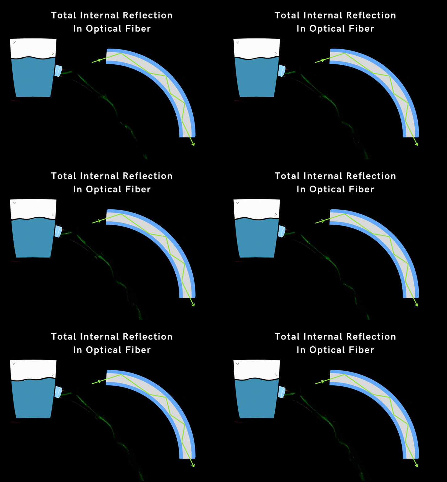
Some important points:
- The core has a higher refractive index to create total internal reflection.
- The critical angle is around 82° for typical fiber materials.
- Light approaching at larger angles than this critical value undergoes total internal reflection.
- This keeps the light confined in the core so it can transmit data over long distances.
In summary, total internal reflection at the core-cladding boundary is crucial to how fiber optics transmit information using light. The refractive index difference enables the total internal reflection effect.
Summary
We explored the key optical phenomena that enable fiber optic communication, including refraction, reflection, refractive index, Snell’s law, critical angle, and total internal reflection. By understanding these concepts, it is clear that total internal reflection within the optical fiber’s glass core is what allows light to carry data over long transmission distances.
The core has a higher refractive index than the surrounding cladding, creating the refractive index mismatch necessary for total internal reflection above the critical angle. This confines the light internally as it propagates down the length of the fiber.
Through careful engineering of the core and cladding materials and geometries, optical fibers actively channel and transmit digital information encoded in light pulses using the principles of critical angle and total internal reflection.
FAQ
How do endoscopes use total internal reflection?
Endoscopes rely heavily on total internal reflection (TIR) to illuminate and image internal organs. Thousands of thin optical fibers bundled together form the endoscope shaft. Light travels down these fibers, bouncing off the inner cladding due to TIR and capturing the organ’s interior. The reflected light then travels back through the fibers, ultimately forming an image for medical professionals to examine.
What characteristic of optical fiber causes total internal reflection?
The key characteristic enabling TIR in optical fibers is the difference in refractive indices between the fiber core (higher index) and cladding (lower index). This difference creates a critical angle, where light rays striking the core-cladding boundary at angles greater than this critical angle undergo TIR instead of refracting into the cladding and escaping the fiber.
What are two ways reflection is involved in fiber optics?
Reflection plays two crucial roles in fiber optics:
∎ Total internal reflection (TIR): As discussed earlier, TIR confines light within the fiber core, allowing for long-distance transmission.
∎ Fresnel reflection: When light encounters the boundary between two media with different refractive indices (e.g., air-to-fiber), a small portion gets reflected. This Fresnel reflection can cause signal loss, especially at connectors and terminations, and needs to be minimized for optimal fiber performance.
Where do we see total internal reflection in real world?
Besides optical fibers, total internal reflection finds applications in various real-world scenarios:
∎ Mirages: When sunlight refracts through hot air layers with varying densities, it can bend and create illusions like mirages in deserts.
∎ Diamonds: The brilliant sparkle of diamonds arises partly from total internal reflection within the gemstone, causing light rays to bounce repeatedly and emerge from different facets.
∎ Fiber optic decorations: Decorative items like fiber optic cables and Christmas trees utilize TIR to guide light along thin fibers, creating captivating visual effects.
Does an optical fiber need a cladding in order for total internal reflection to occur?
Yes, a cladding is essential for total internal reflection to occur in an optical fiber. The difference in refractive indices between the core and cladding creates the necessary conditions for TIR. Without a cladding, light rays entering the core would simply refract out at the boundary, preventing efficient light transmission through the fiber.


