Telecommunications relies heavily on the seamless transmission of data through optical fibers. At the heart of this process are optical sources – tiny semiconductor devices that convert electrical signals into optical signals. This article will explore the major types of optical sources used in telecommunications and their characteristics.
Table of Contents
Optical Sources and Optical Fiber
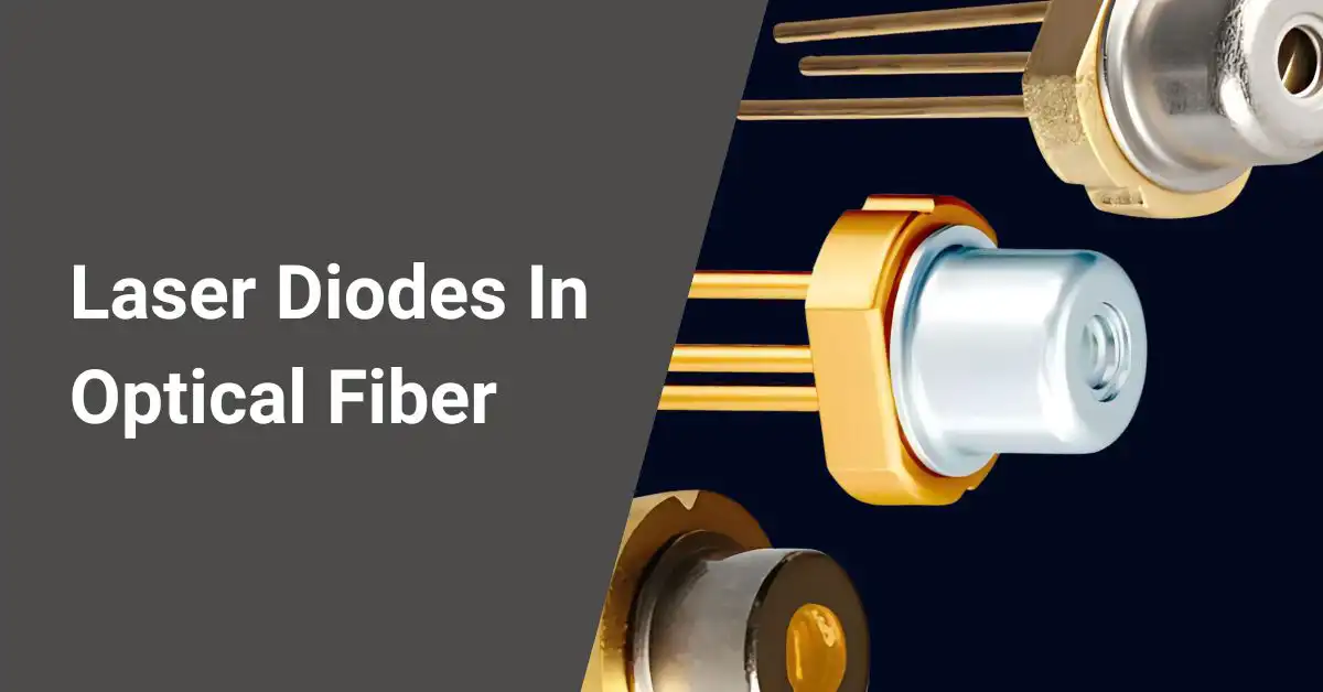
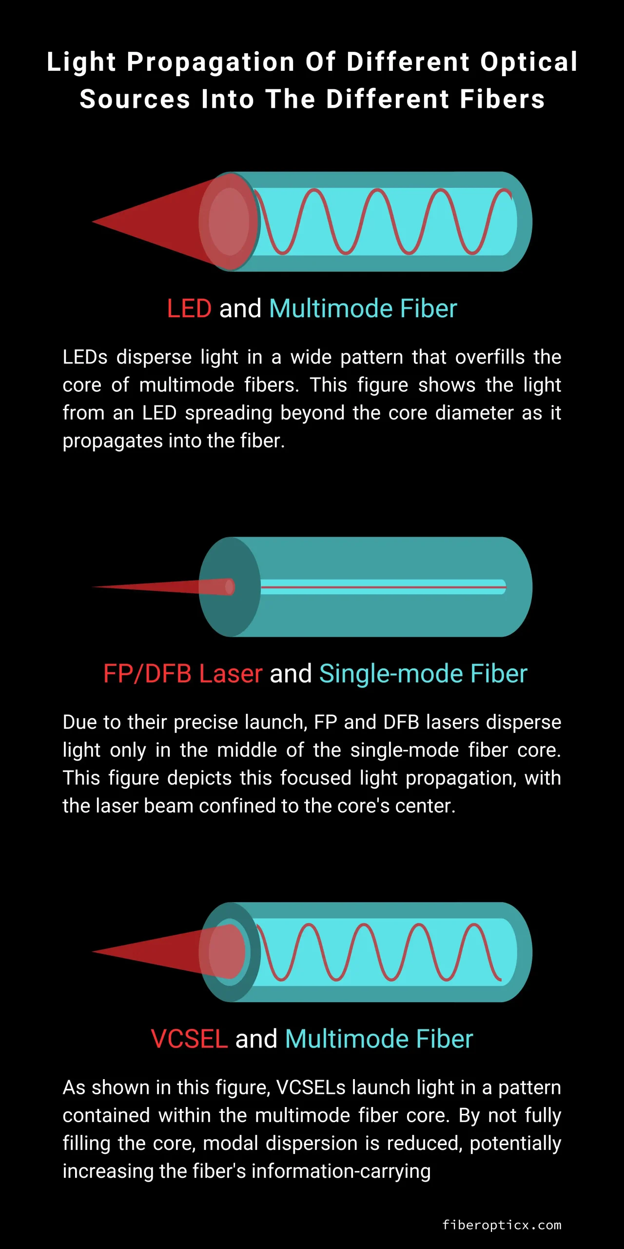
The four main types of optical sources are LEDs, Fabry-Perot (FP) lasers, Distributed Feedback (DFB) lasers, and Vertical Cavity Surface-Emitting Lasers (VCSELs). All convert electrical signals into optical signals but differ in their designs and capabilities.
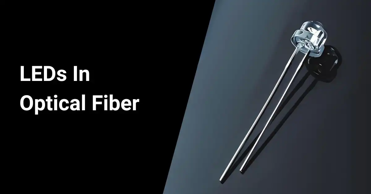
- LEDs are tiny semiconductor devices about the size of a grain of sand. They emit light from the surface of the chip and are commonly used with multimode fibers.
- VCSELs, on the other hand, are a type of semiconductor laser diode with laser beam emission perpendicular from the top surface. Their output pattern is well-suited for multimode fibers.
- DFB lasers are known for their stability and are frequently used in high-speed fiber-optic telecommunications where clean single-mode operation is required.
- FP lasers, also known as Fabry–Pérot interferometers, emit from the side of the chip. They are commonly used in optical modules.
The table contents below show typical fiber optic source specifications:
| Characteristic | LED | FP Laser | DFB Laser | VCSEL |
|---|---|---|---|---|
| Spectral Width (nm) | 20-50 | 2-5 | 0.1-1 | 0.1-1 |
| Wavelength (nm) | 850,1300 | 850,1310 (1280-1330) 1550 (1480-1650) | 1500 (1480-1650) | 850 |
| Typical Output Power (mW) | 0.1-1 | 1-10 | 1-10 | 0.1-1 |
| Fiber Types | Multimode | Single-mode, Multimode | Single-mode | Multimode |
| Power into Fiber (dBm) | -30 to -10 | 0 to +25 | 0 to +25 | -10 to 0 |
| Typical Fiber Diameter (μm) | 50/62.5 | 8-10 | 8-10 | 50/62.5 |
| Bandwidth | <250 MHz | >10 GHz | >10 GHz | >10 GHz |
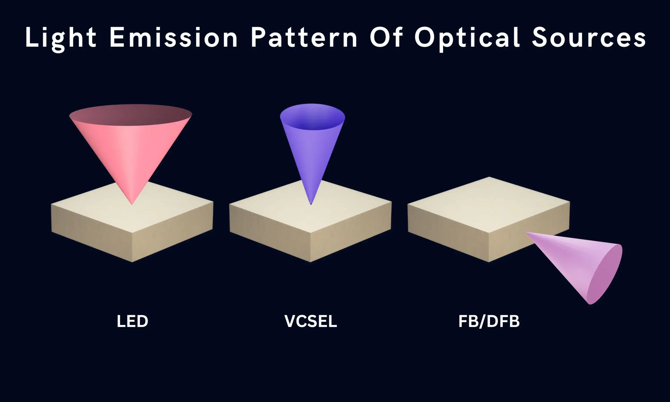
The light emission pattern of these optical sources varies, as mentioned above in the table. LEDs disperse light in a wider pattern than the fiber core, while lasers emit a more focused beam compatible with single-mode fibers.
Coupling Light into Fiber
Coupling light to fiber is the most difficult and costly part of manufacturing a real LED or laser. There are six common methods:
- Use of a GRIN (Graded-Index) lens
- Direct coupling
- Fixing a ball lens to the end of a fiber
- A ball lens
- Using a thin lens
- Using an aspheric lens
This image illustrates these common methods of coupling light into fiber.
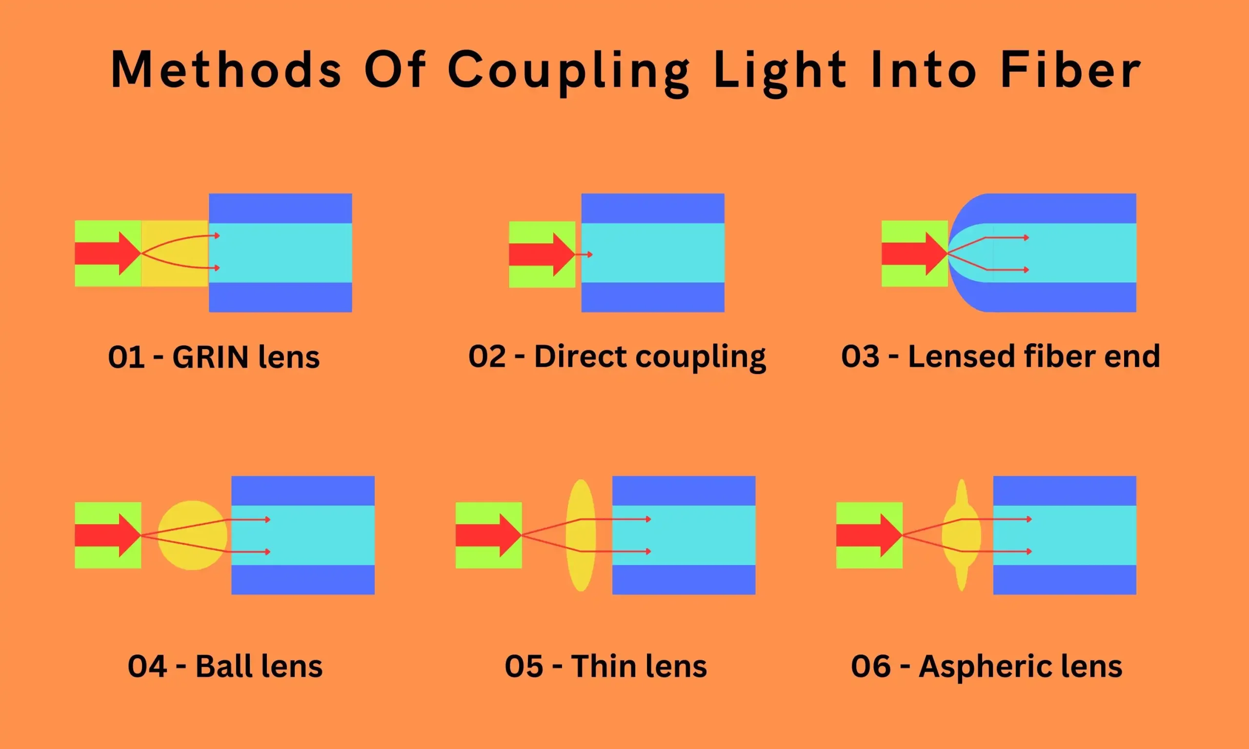
The choice of coupling method depends on factors such as the source type, fiber type, and the required coupling efficiency. For example, direct coupling may be suitable for some LED-to-multimode fiber connections, while the use of a GRIN lens or aspheric lens may be necessary for efficient coupling of a laser source to a single-mode fiber.
Proper coupling is crucial, as any light that fails to enter the fiber core is essentially wasted, reducing the overall efficiency and performance of the optical link. As such, optimizing the coupling technique is a critical aspect of optical fiber system design and manufacturing.
Optical Source Characteristics
Let’s dive into the key characteristics that determine how suitable an LED or a laser is for a particular application.
Here is a comparison table of the characteristics of laser and LED optical sources.
| Characteristic | Laser | LED |
|---|---|---|
| Output Power | Small emission diameter and NA for efficient coupling into the fiber | Emits more power than a laser below the lasing threshold |
| Output Pattern | Typical values are 6 dB to 12 dB | Wider output pattern that overfills fiber core |
| Current | Threshold current – 5mA to 40 mA | Drive current – 50mA to 100 mA (Peak) |
| Spectral Width | Narrow (0.01 nm to 10 nm) | Broad (tens of nanometers) |
| Coupled power | High | Moderate |
| Speed (Rise/Fall Time) | Fast (< 1 ns) | Slower (nanoseconds range) |
| Extinction Ratio | Often works like a normal digital system (on/off) | Often works like normal digital system (on/off) |
| Fiber type | Single-mode and Multimode | Multimode only |
| Lifetime | Shorter expected lifetime | Longer expected lifetime |
| Available wavelengths | 0.78 to 1.65 mm | 0.66 to 1.65 mm |
| Ease of Use | More expensive, less reliable, requires complex transmitter circuits | Less expensive, more reliable, easier to use |
Output Power
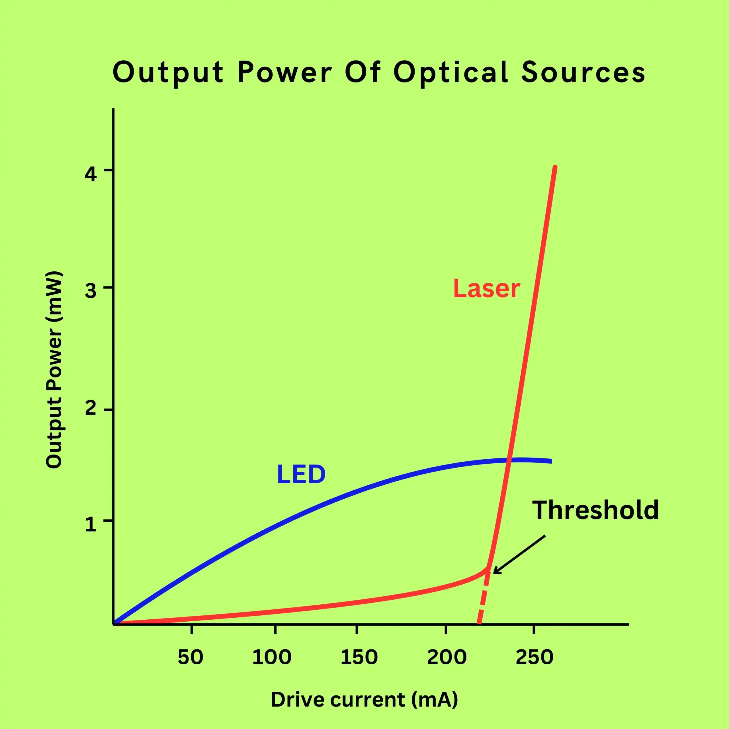
Output power is the optical power emitted at a specified drive current. An LED emits more power than a laser operating below the lasing threshold. However, above the lasing threshold, the laser’s power increases dramatically with increases in drive current, as shown below.
Optical power output is calculated by multiplying the optical energy per pulse by the pulse repetition rate. The formula is P = E/t, where P is the power in watts, E is the energy in joules, and t is the time in seconds.
In fiber optic communications, optical power is often specified in dBm, which represents decibels relative to the reference power of 1 mW.
Specialized equipment like optical power meters are used to measure optical power. Some can handle multiple kilowatts of laser power, while others can measure very low powers, such as microwatts or nanowatts.
There are two types of optical power measurements:
- Absolute: The power output of a transmitter or the input to a receiver.
- Relative: The difference between the power coupled into a component (like a cable or connector) and the power transmitted through it.
The key takeaway? While LEDs emit more power initially, lasers can significantly outperform LEDs in terms of output power once they reach the lasing threshold. This makes lasers a popular choice for high-speed, long-distance fiber optic communication systems.
Output Pattern
The output pattern of the light is crucial in fiber optics. As light leaves the chip, it spreads out. Only a portion actually couples into the fiber. A smaller output pattern allows more light to be coupled into the fiber efficiently.
A good source should have a small emission diameter and a small numerical aperture (NA). The emission diameter defines how large the area of the emitted light is, while the NA defines at what angles the light is spreading out.
If either the emitting diameter or the NA of the source is larger than that of the receiving fiber, some optical power will be lost. The below image shows typical emission patterns for an LED and a laser.
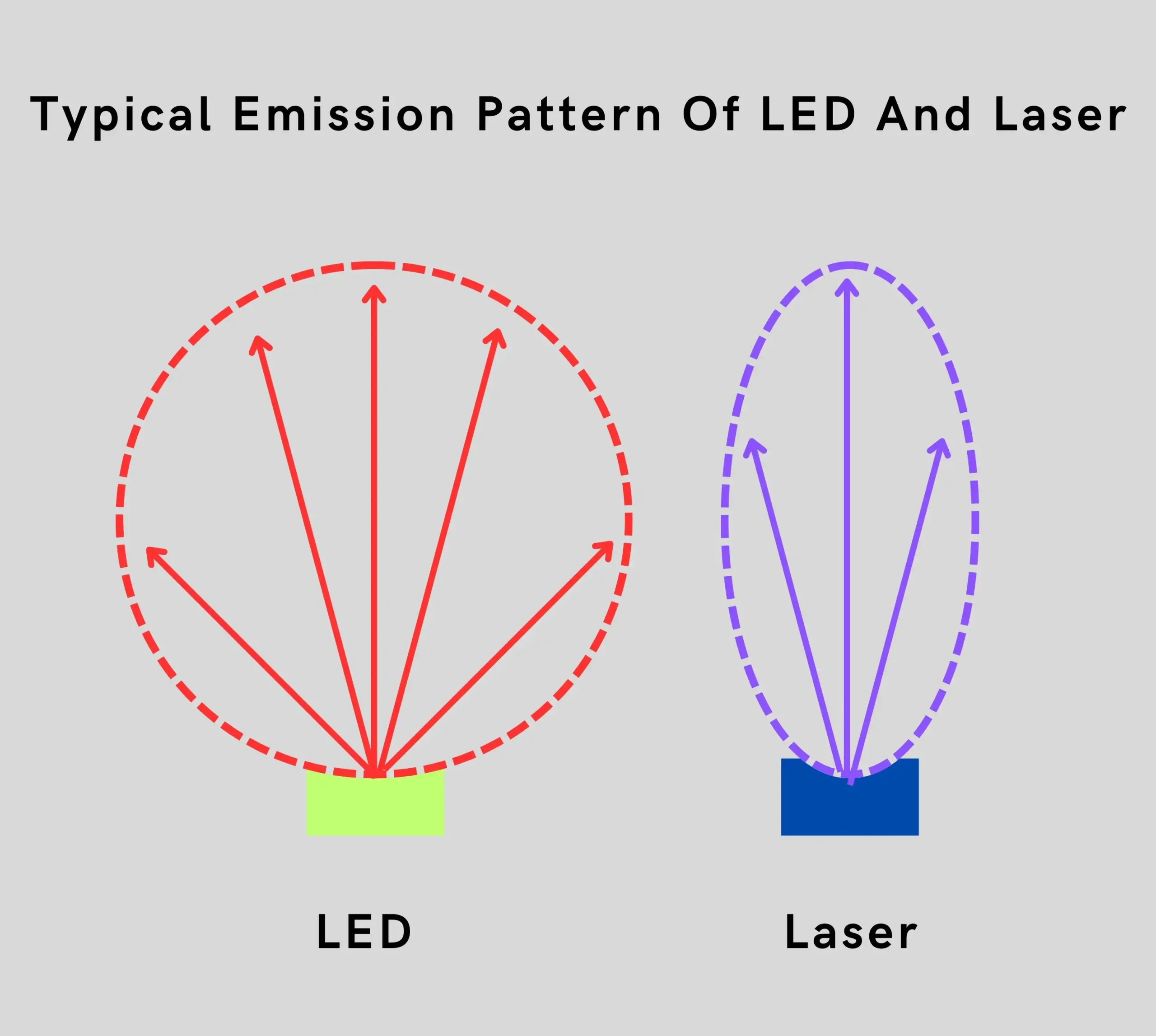
A single-mode fiber requires an FP or DFB laser source, as the laser provides a small, intense beam of light compatible with the small core of the fiber. Multimode fibers, on the other hand, require either LED or VCSEL sources.
It’s worth noting that the output of most FP and DFB lasers is elliptical rather than circular, while the VCSEL emits a circular pattern.
Spectral Width
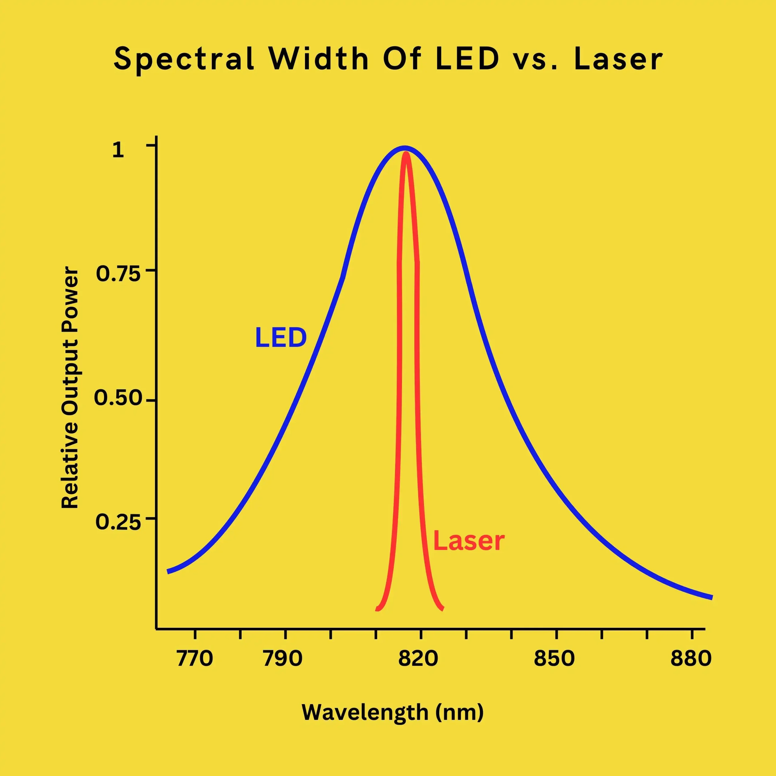
Lasers and LEDs don’t emit a single wavelength; they emit a range of wavelengths known as the spectral width. The spectral width is measured at 50% of the maximum amplitude of the peak wavelength.
The spectral width of a laser is substantially narrower (0.01 nm to 10 nm) than that of an LED (tens of nanometers). For example, if an LED has a peak wavelength of 620 nm and a spectral width of 30 nm, its output ranges from 605 to 635 nm.
At 620 nm, material dispersion can be estimated as 0.1 ns/km for each nanometer of source spectral width. An LED with a 30 nm spectral width results in 3 ns of dispersion over a 1-km run.
The following image clearly shows that the spectral width of a laser is much narrower than that of an LED.
While spectral width may not be crucial for fiber optic links running under 100 MHz for only a few kilometers, it is especially important in high-speed, long-distance, single-mode systems because the resulting dispersion is the principal limiting factor on system speed.
Speed
The source must turn on and off fast enough to meet the bandwidth requirements of the system. Source speed is specified by rise and fall times. Lasers have rise times of less than 1 ns, whereas slower LEDs have rise times in the nanoseconds range.
A rough approximation of bandwidth for a given rise time is defined as:
Bandwidth (GHz) = 0.35 / Rise Time (ns)
For example, a 1-ns rise time allows 350-MHz operation, and a 5-ns rise time allows 70-MHz operation. Lasers’ faster rise times make them better suited for high-speed applications compared to LEDs.
Extinction Ratio
The extinction ratio (ER) is the ratio of the power transmitted when sending a 1 bit to the power transmitted when sending a 0 bit. It’s represented by the symbol re.
The practical effect of the extinction ratio is to cause a power penalty. The receiver must receive more optical power than if the laser is turned off completely. This power penalty can be in the range of 1 dB, depending on the application.
In normal digital systems, a digital one (1) is interpreted as being on, and a digital zero (0) as being off. However, laser systems never turn completely off because this slows the laser down.
The fact that the laser does not turn off means there is less difference between a 1 and a 0. Instead, a laser can be rapidly modulated between two levels above the lasing threshold.
The ER is used to calculate the optical modulation amplitude (OMA), which is sometimes specified in place of receiver sensitivity. It can also affect the link budget, with small changes in ER making a significant difference in the power required to maintain a constant bit error rate (BER).
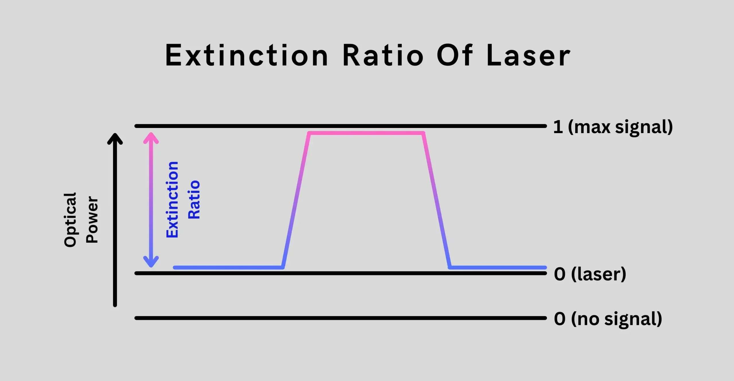
The above image illustrates the idea of extinction ratio, showing the ratio between one “on” level (P1) and the “off” level (P2) as
\(ε=10\log\left(\frac{P_1}{P_2}\right)\)
Typical values range from 6 dB to 12 dB, with a higher value being better.
Lifetime
The expected operating lifetime of a source runs into millions of hours. However, over time, the output power decreases due to increasing defects in the device’s crystalline structure. The lifetime of the source is typically taken to the end when the peak output power is reduced by 50% or 3 dB.
For example, if an LED is emitting a peak power of 1 mW, it’s considered at the end of its lifetime when its peak power becomes 500 μW.
Ease of Use
Although a laser provides better optical performance than an LED, lasers are more expensive, less reliable, and harder to use. They also have a shorter expected lifetime than LEDs and require more complex transmitter circuits.
The output power of a laser can change significantly with temperature. Maintaining proper output levels over the required temperature range requires circuitry that detects changes in output and adjusts the drive current accordingly.
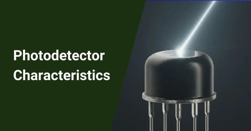
One method of maintaining these levels is with a photodiode to monitor the light output on the back facet of the laser. The photodiode’s current changes with light output variations, providing feedback to adjust the laser drive current.
In contrast, LEDs are generally more straightforward to use and integrate into systems, making them a popular choice for many applications despite their performance limitations compared to lasers.
Overall, while lasers offer superior optical performance, their complexity, cost, and reliability considerations mean that LEDs remain a practical choice in many situations, particularly where high speeds and long distances are not required.
Conclusion
In summary, optical sources play a vital role in fiber optic communication systems by converting electrical signals to optical signals.
LEDs, FP lasers, DFB lasers, and VCSELs each have unique characteristics that make them suitable for different applications. When choosing an optical source, key considerations include output power, spectral width, speed, and ease of use.
Lasers generally offer higher speeds and narrower spectral widths needed for long-distance, high-speed systems.
However, LEDs remain a practical option for many uses due to their lower cost and complexity. Moving forward, continued advancements in optical source technology will help unlock more capabilities for fiber optic communication networks worldwide.
FAQ
How do the characteristics of optical sources and optical fibers influence each other?
These characteristics work together:
➤ Wavelength: Source wavelength should match the fiber’s low-loss windows for best transmission.
➤ Power & NA: Enough source power and high fiber NA allow for efficient light coupling.
➤ Linewidth & Dispersion: Narrower linewidth reduces signal distortion from dispersion in the fiber.
➤ Bandwidth: Source modulation bandwidth should be less than or equal to the fiber bandwidth to avoid data rate limitations.
What are the advantages of using laser diodes compared to LEDs in optical fiber communication?
Laser diodes offer significant advantages over LEDs:
➤ Higher Power: They can transmit signals over longer distances due to their stronger light output.
➤ Narrower Linewidth: This translates to clearer signals and enables higher data transmission rates.
➤ Wider Modulation Bandwidth: Allows for faster switching of light intensity for carrying more data.
Are there any other types of optical sources besides laser diodes and LEDs?
Yes, there are other emerging options for optical sources with specific applications:
➤ Superluminescent Diodes (SLDs): Offer a broader spectrum than laser diodes but with higher power than LEDs, useful for some sensor applications.
➤ Quantum Cascade Lasers (QCLs): Operate at longer wavelengths (mid-infrared), enabling applications in spectroscopy and gas sensing.
How does temperature affect the performance of optical sources?
Temperature fluctuations can impact optical sources in a few ways:
➤ Wavelength Shift: As the temperature increases, the operating wavelength of the source might shift, potentially causing signal distortion.
➤ Threshold Current: The minimum current required for laser operation can increase, affecting efficiency and power consumption.
➤ Lifetime: Higher operating temperatures can accelerate the degradation process and shorten the lifespan of the source.
What is the future outlook for optical sources in fiber optic communication?
The development of optical sources continues to focus on:
➤ Higher Power and Efficiency: Ongoing research aims to improve the power output and efficiency of laser diodes, enabling even longer reach and higher data capacities.
➤ Integration with Other Technologies: Integrating laser diodes with modulators and detectors on a single chip can lead to more compact and efficient communication modules.
➤ New Source Materials: Exploring novel materials for laser diodes could lead to even higher efficiencies and potentially new functionalities.