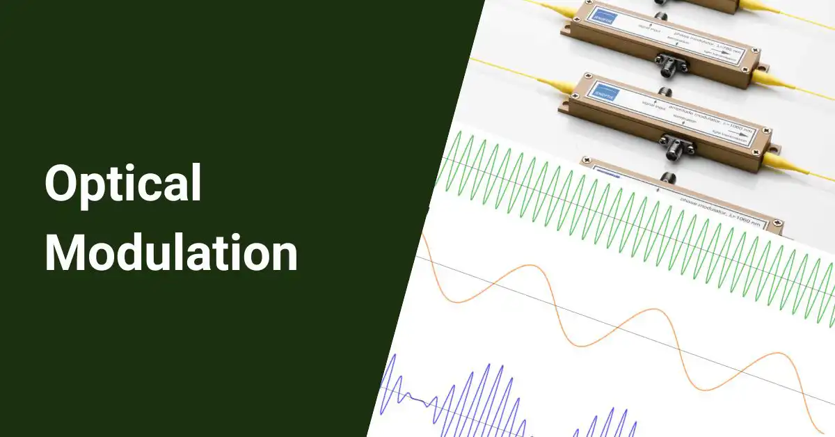
Optical modulation is a crucial process that allows control over an optical wave or encoding of information on a carrier optical wave. The inverse process that recovers the encoded information from the modulated optical wave is called demodulation. Optical modulation enables many key functions in optical communications systems and networks.
There are various types of optical modulation schemes and techniques, which can be categorized and described using several characteristics.
Table of Contents
Optical Modulation
Optical modulation involves actively modifying one or more properties of an optical wave or beam to encode information or control its behavior. Demodulation then extracts the encoded information or desired wave behavior from the modulated optical signal at the receiving end.
Optical modulation schemes differ in terms of the following:
- Optical wave parameter modulated
- Method of modulation
- Material properties leveraged
- Physical effects involved
- Modulator device structure
And more, as covered in the sections below.
Optical-field Parameter Being Modulated
The key optical wave parameter that is modulated defines the type of modulation scheme used. Major categories as per modulated parameters are:
- Phase modulation: The phase of the optical carrier wave is varied to encode information while its amplitude remains constant. This can be implemented via refractive index modulation.
- Frequency modulation: The frequency of the optical carrier wave is varied based on the message signal, while its amplitude and phase remain unchanged.
- Polarization modulation: Properties related to the vector nature of the optical wave’s electric field, like polarization state, direction, and ellipticity, are modulated.
- Amplitude modulation: The amplitude or intensity of the optical wave is directly modulated while keeping its frequency and phase constant. Absorption and transmittance modulation can enable this.
- Spatial modulation: Spatial properties of the optical wave, like mode patterns, beam shape/direction, and propagation trajectories, are modulated. This requires modulating guided waves.
- Diffraction modulation: Parameters related to diffraction effects like diffraction efficiency and angles are modulated via altering optical geometries.
The specific optical parameter modulated determines the type of information encoding possible and the appropriate modulation-demodulation methods to be implemented. Appropriate photodetectors and decoding circuitry are also needed to recover the message from the modulated optical signal. These design choices depend on the target application and link requirements.
Information Encoded Form In Modulation
Optical modulation schemes differ in how information is encoded on the carrier wave – either analog or digital:
Analog modulation uses a continuously varying analog sine wave carrier that gets modulated by the analog message/information signal. Key analog modulation types are:
- Amplitude Modulation (AM) – Carrier amplitude varies based on the message signal
- Frequency Modulation (FM) – Carrier frequency varies based on the message signal
- Phase Modulation (PM) – Carrier phase relative to reference carrier phase varies
Additionally:
- Pulse Amplitude Modulation uses a pulse train carrier with discrete amplitude levels based on the message signal
Digital modulation has discrete modulation states derived from a digital bitstream message signal. Digital modulation types covered later include:
- Amplitude Shift Keying (ASK)
- Frequency Shift Keying (FSK)
- Phase Shift Keying (PSK)
Key Tradeoffs: Analog modulation enables a better signal-to-noise ratio for audio/voice signals but is more noise-sensitive. Digital modulation resists noise better and works for computer data streams.
Amplitude Modulation
Amplitude modulation (AM) varies the amplitude of a high-frequency sine wave carrier based on the amplitude of the modulating message signal while keeping the carrier frequency and phase constant.
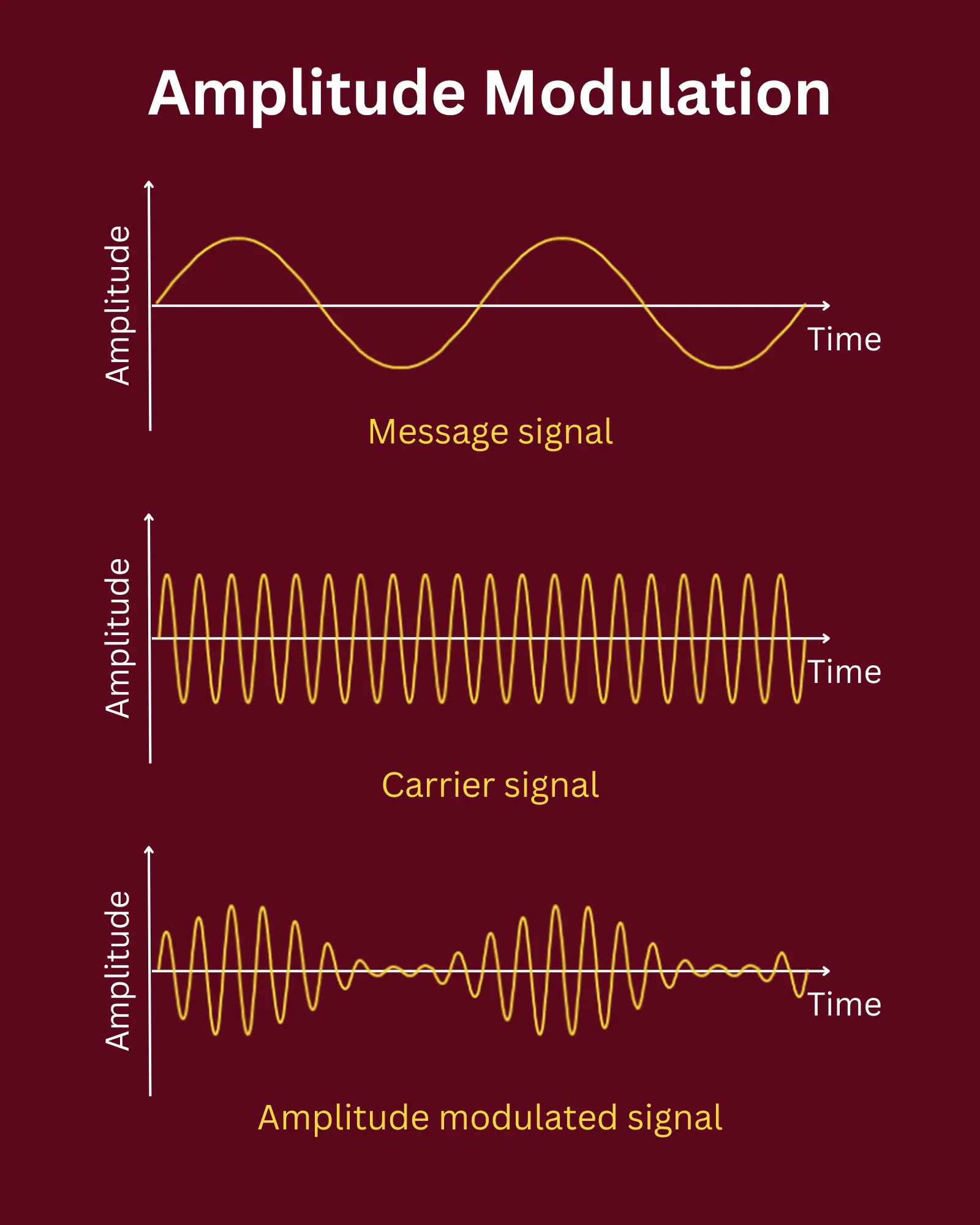
AM technique properties:
- High-frequency carrier wave with constant frequency and phase.
- Carrier amplitude is proportional to the instantaneous amplitude of the modulating/message signal.
- Applicable for transmission of audio/voice band message signals.
This amplitude variation encodes the full message signal continuously on the carrier wave as an analog representation.
Demodulation then recovers this audio/data message signal from the modulated carrier at the receiver.
Frequency Modulation
Frequency modulation (FM) keeps the carrier amplitude constant while varying its frequency proportional to the amplitude of the modulating message signal.
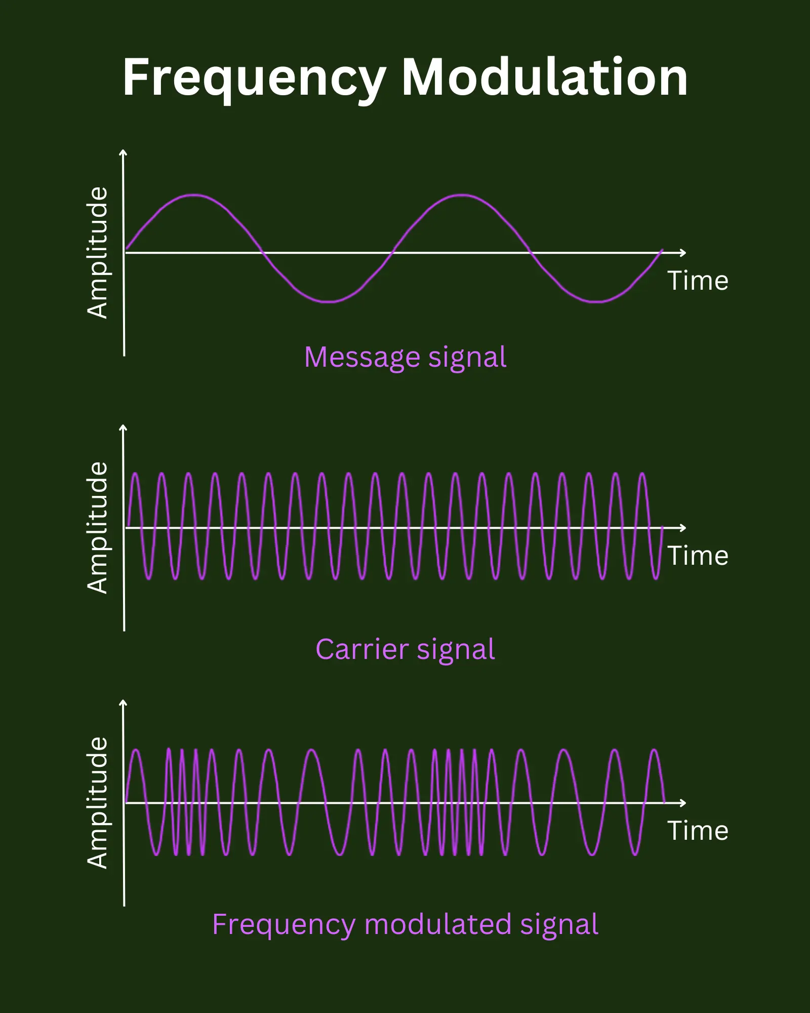
Key FM attributes:
- Constant carrier wave amplitude.
- Carrier frequency shifted up/down from center/rest frequency based on the amplitude of the modulating message signal.
- Improves signal-to-noise ratio and noise resistance.
- Applicable for high-fidelity music/audio transmission.
The analog message signal gets encoded onto corresponding variations in instantaneous carrier frequency. Demodulation then maps carrier frequency back to the message signal.
Phase Modulation
Phase modulation (PM) keeps the carrier amplitude constant while varying its phase relative to a reference carrier phase based on the amplitude of the modulating message signal.
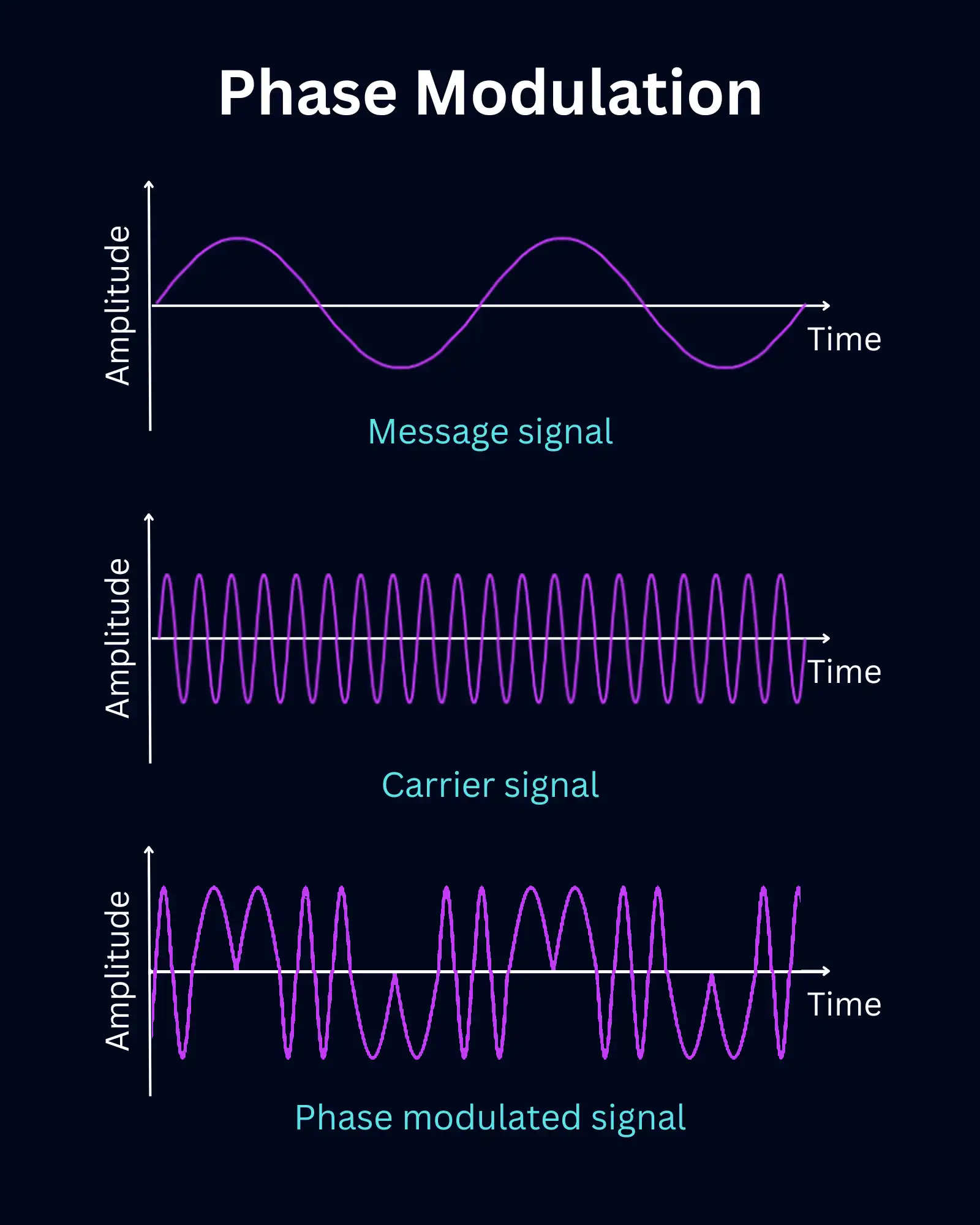
Key attributes:
- Carrier wave with fixed amplitude.
- The carrier phase shifted from the reference phase by an amount proportional to the instantaneous amplitude of the message signal.
- Phase is the main parameter modulated.
The message signal gets encoded as analog variations in the carrier wave phase over time while keeping the amplitude unchanged. Demodulation then maps the phase back to the message signal.
Analog Pulse Modulation
Analog pulse modulation uses a pulsed carrier wave and modulates the parameters of these pulses based on a continuous message signal.
Types are:
- Pulse Amplitude Modulation (PAM): Pulses modulated in amplitude
- Pulse Width Modulation (PWM): Pulse width varied
- Pulse Position/Location Modulation: Pulse position in time-shifted
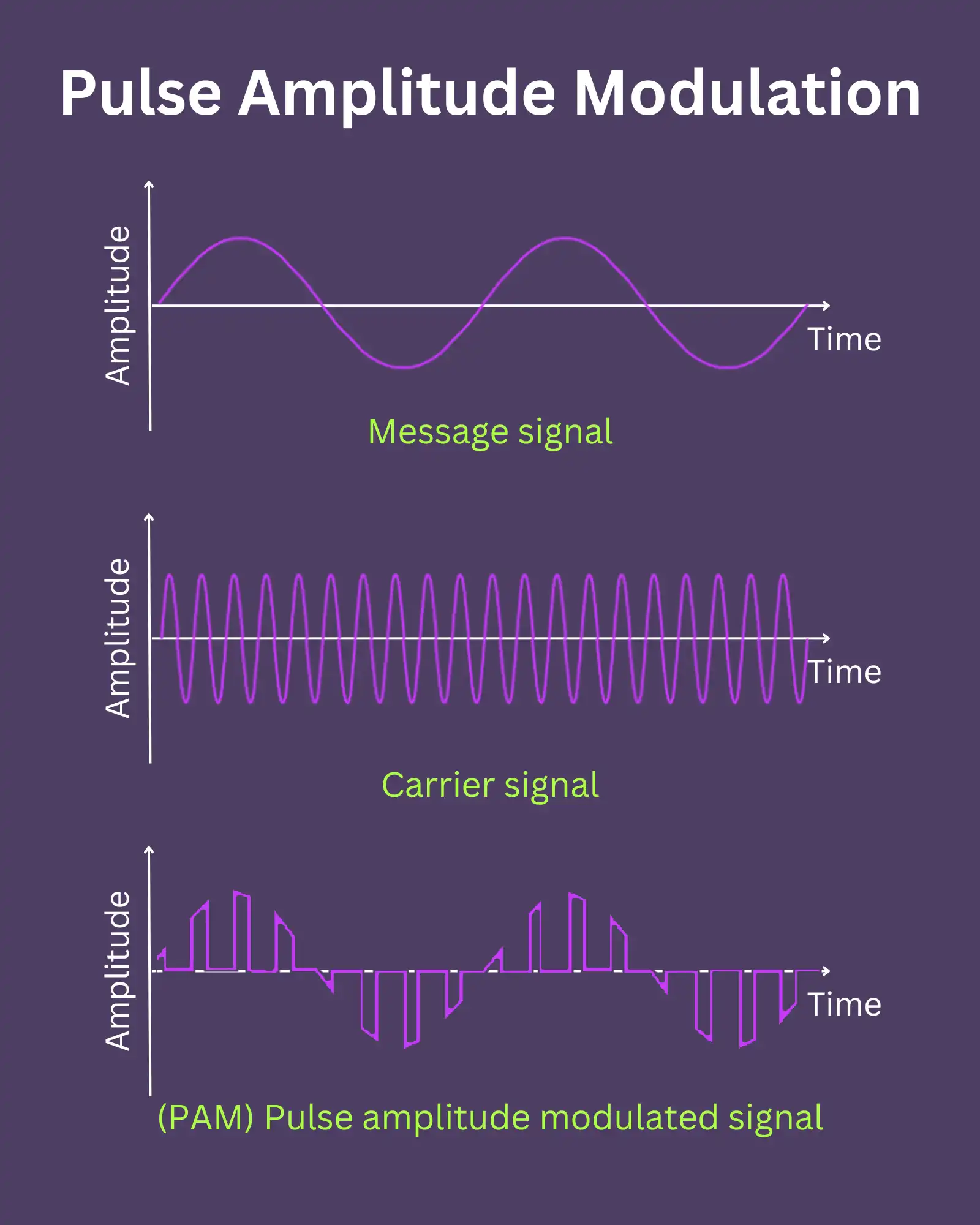
This allows the encoding of analog message signals using variations in the parameters of a pulse train carrier wave.
Amplitude Shift Keying
Amplitude Shift Keying (ASK) is a digital modulation technique that represents binary data by shifting the amplitude of a carrier wave among discrete levels.
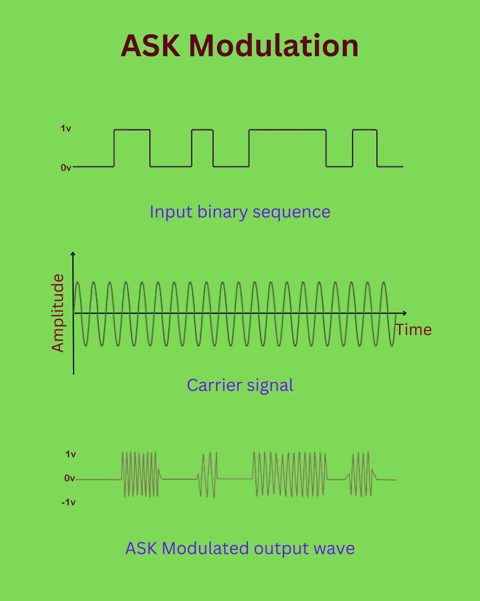
- Carrier modulated between two amplitudes:
- High amplitude represents binary 1
- Zero amplitude represents binary 0
- Amplitude shift encodes binary message signal
Demodulation detects amplitude levels to recover the digital messages.
Frequency Shift Keying
Frequency Shift Keying (FSK) is a digital modulation technique that shifts the frequency of a constant amplitude carrier between discrete values to encode binary data.
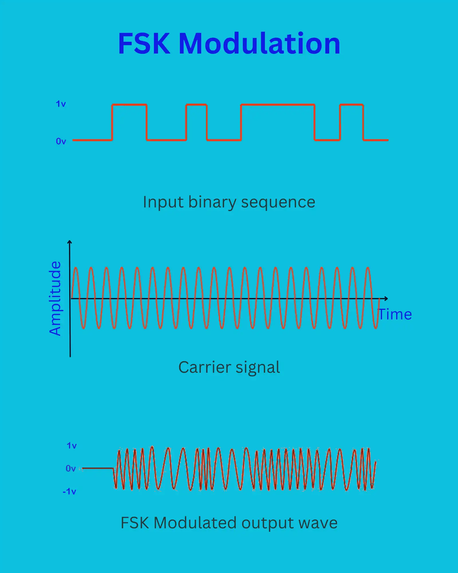
- Carrier modulated between two frequencies:
- High frequency represents binary 1
- Low frequency represents binary 0
- Frequency shifts encode binary message signal
Demodulation detects frequency levels to recover the digital messages.
Phase Shift Keying
Phase Shift Keying (PSK) is a digital modulation technique that shifts the phase of a constant amplitude carrier wave between discrete values to encode binary data.
- Carrier phase is modulated between two or more discrete phases.
- Each phase shift represents a unique bit pattern.
- Phase changes encode digital message signals.
Demodulation detects phase shifts relative to a reference carrier to recover the digital message.
Binary Phase Shift Keying
Binary Phase Shift Keying (BPSK) is the simplest PSK scheme with just two phase states – 0 and 180 degrees.
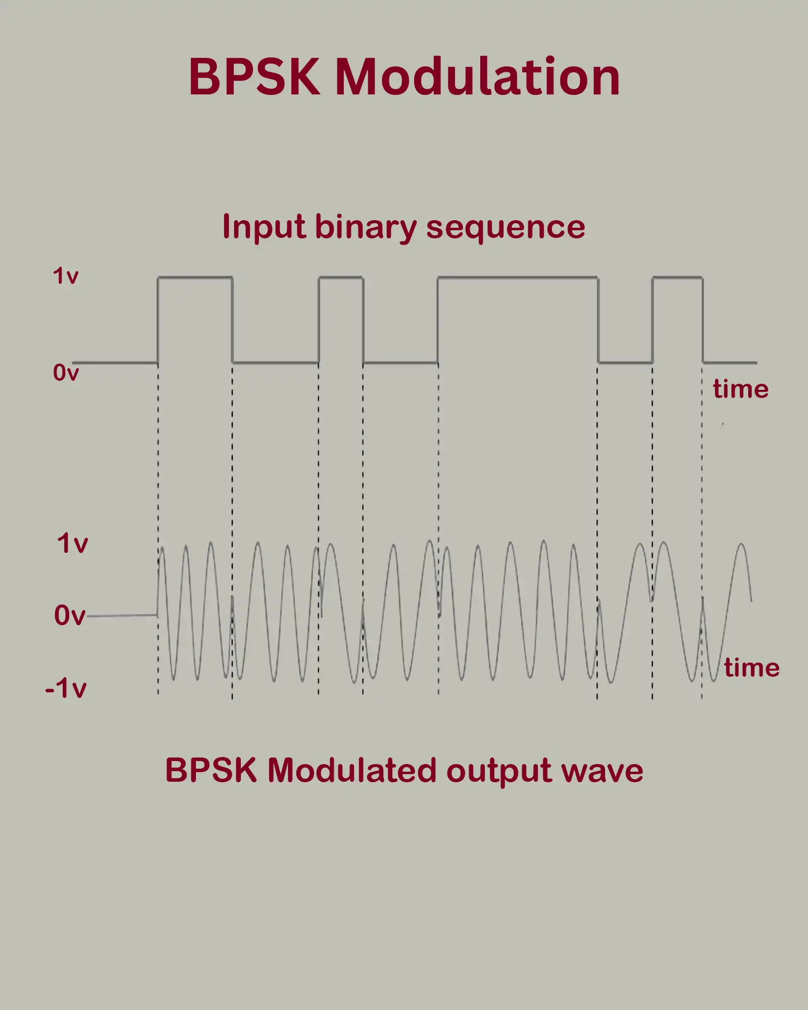
BPSK properties:
- Carrier phase flipped between 0° and 180°.
- Represents a binary digital modulation (1 bit per symbol).
- 180° phase shift represents binary 1.
- No phase shift indicates binary 0.
So the binary signal directly modulates the 180° carrier phase shifts.
Quadrature Phase Shift Keying
Quadrature PSK (QPSK) modulates the carrier wave among four 90-degree spaced phase states to encode 2 bits per symbol.
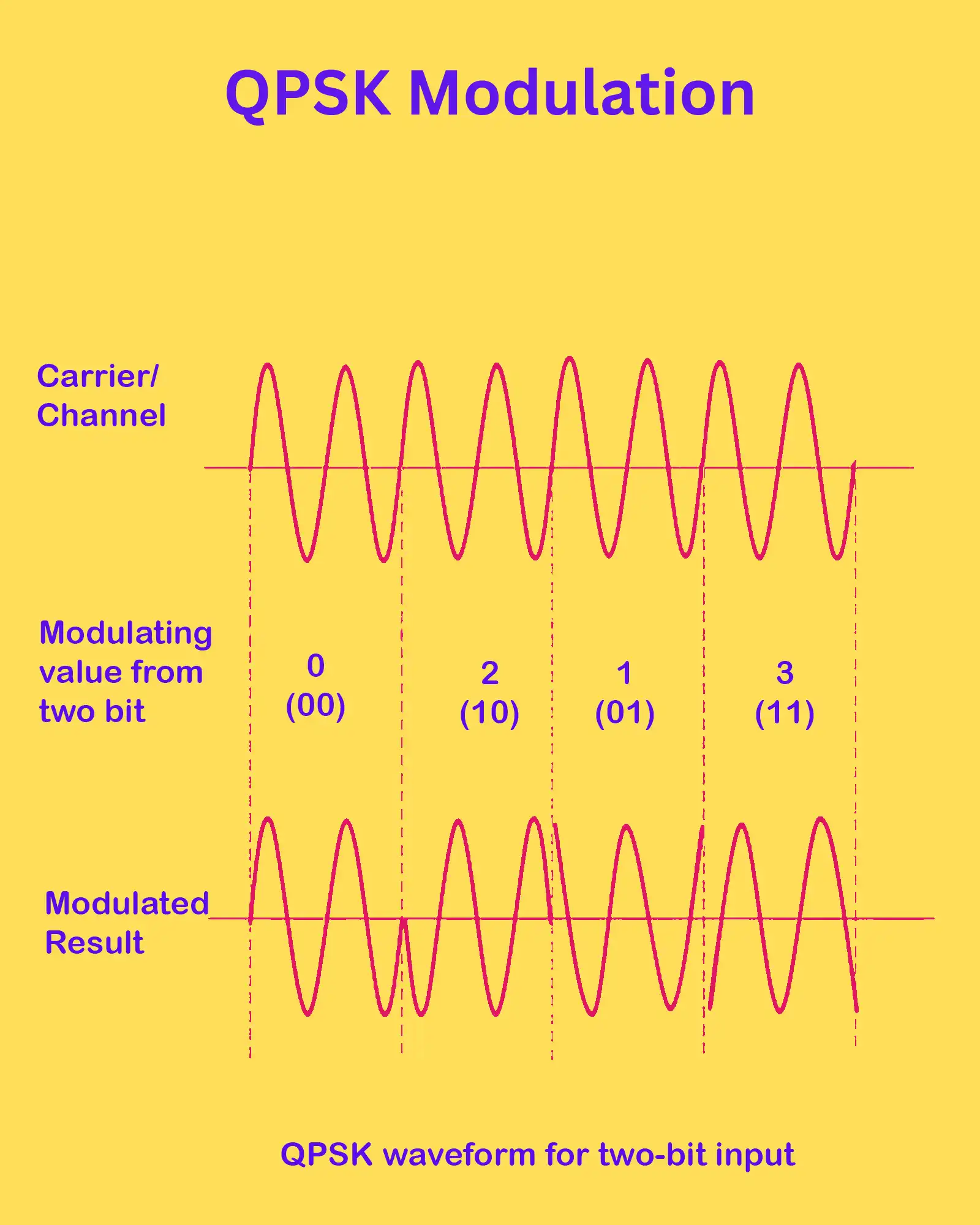
QPSK attributes:
- 4 possible carrier phases: 0°, 90°, 180°, 270°.
- Each phase shift keys a unique 2-bit input symbol.
- Double the bits per symbol compared to BPSK.
- Symbols can map to bitpairs directly.
Provides higher spectral efficiency over BPSK.
Differential Phase Shift Keying
Differential PSK (DPSK) encodes input binary data as carrier phase shifts relative to the previous phase rather than a fixed reference.
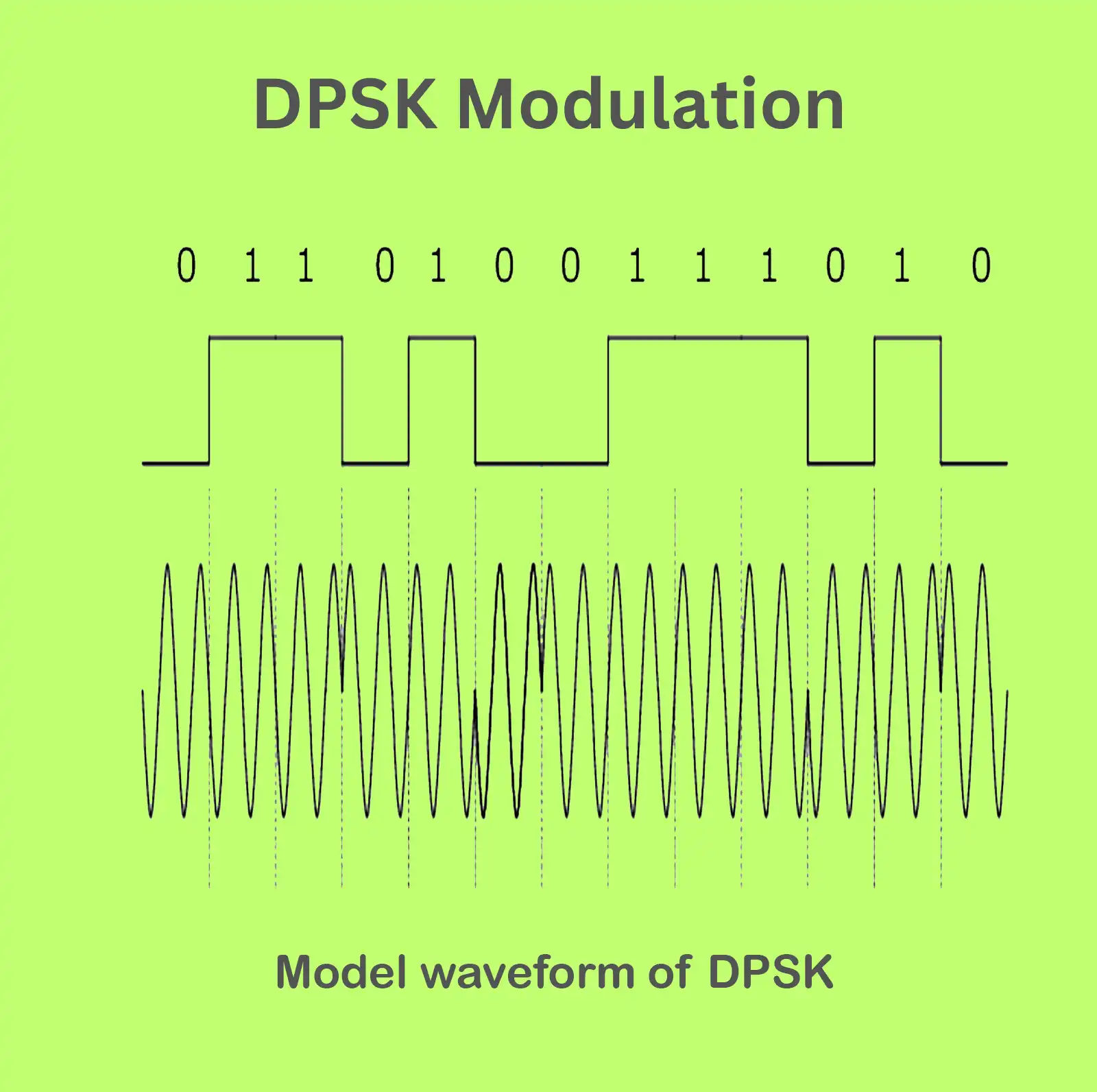
DPSK properties:
- No reference phase is needed.
- Phase of current bit interval shifted:
- 180° relative to the previous if the input is 1.
- Stays same as the previous if the input is 0.
- Phase shifts are relative.
Robust to slowly varying phase drifts.
The Way Of Modulation Performing
Optical modulation can be implemented through two main approaches:
Direct Modulation
Direct modulation directly superimposes the modulating message signal onto the driving current of an optical source like an LED or laser to modulate its output.
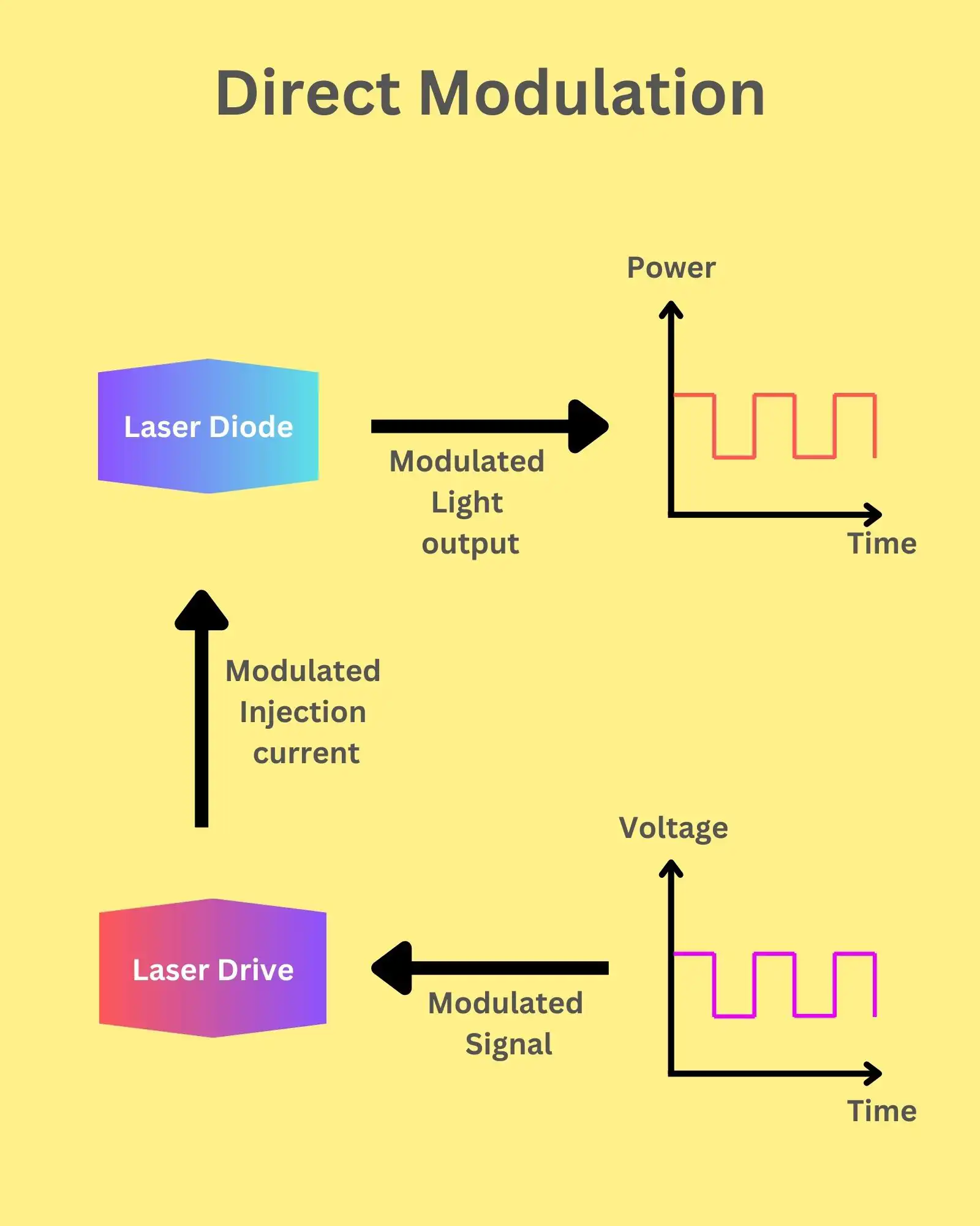
- Performs modulation and light generation concurrently.
- Optical source bias current is modulated directly by the message signal.
This leads to proportional modulation of:
- Output amplitude/intensity
- Frequency/wavelength
- Phase
Implementation:
- The message signal is applied together with the DC bias current to modulate the optical source directly.
- Simple and cost-effective.
Drawbacks:
- Modulation bandwidth limited by optical source dynamics
- Higher intensity noise
- Restricts available optical source types
External Modulation
External modulation uses a separate optical modulator component or setup while keeping the optical source drive current constant.
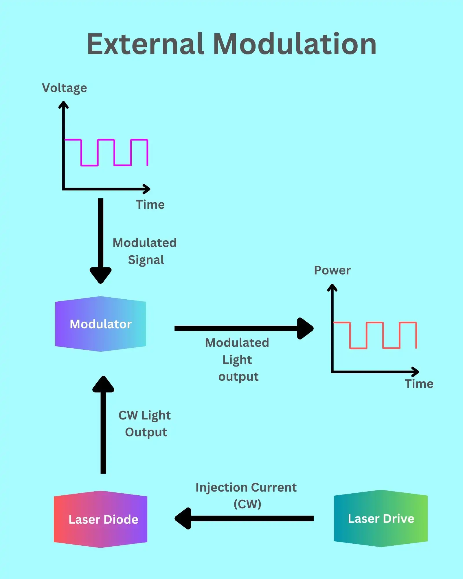
- Optical source provides constant intensity output.
- Separate external modulator encodes the message signal.
Enables:
- Independent optimization of optical source and modulator.
- High modulation speed and bandwidth.
- Lower noise.
- Greater choice of modulation type.
Implementation:
- Optical source is driven at a constant current to output constant intensity.
- External modulator varies light properties based on message signal.
Modulator Material Susceptibility
Optical modulation works by varying the optical susceptibility of the modulator material to alter its refractive/absorptive properties.
Susceptibility has:
- Real part – Determines the refractive index
- Imaginary part – Determines absorption
Modulation types:
- Refractive modulation: Varies the real part of susceptibility to modulate refractive index.
- Absorptive modulation: Varies imaginary part of susceptibility to modulate absorption coefficient.
Refractive modulation example implementations:
- Electro-optic modulation
- Acousto-optic modulation
- Magneto-optic modulation
Absorptive modulation example:
- Electro-absorption modulation
Physical Mechanism Of Optical Modulation
Different physical effects enable varying optical susceptibility for modulation:
- Electro-optic effect: Electric field applied changes the refractive index (Pockels effect).
- Acousto-optic effect: Sound/acoustic wave propagates through a medium, varying refractive index.
- Magneto-optic effect: External magnetic field changes medium refractive index and polarization.
- Electro-absorption: Electric field applied changes absorption (Fraz-Keldysh & Stark effects).
The physical method determines suitable materials, device structures, and external modulation signals.
Geometric Relation Of Optical Modulation
The direction of the applied modulating signal relative to the optical wave propagation direction defines modulation types:
- Transverse modulation: Modulating signal oriented perpendicular to the light propagation direction.
- Longitudinal modulation: Modulating signal oriented parallel to the light propagation direction.
Transverse modulation example devices:
- Electro-optic modulators
- Magneto-optic modulators
Longitudinal modulation examples:
- Acousto-optic modulators
- Electro-absorption modulators
Orientation determines suitable effects and materials for modulation.
Structure Of Optical Modulator
Modulators are designed to modulate either guided or free-space optical waves:
- Bulk modulators: Modulate free-space beams.
- Waveguide modulators: Modulate guided waves in waveguides.
Bulk modulator examples:
- Acousto-optic modulators
- Early electro-optic crystals
Waveguide modulator examples:
- Integrated photonics modulators
- Electro-absorption modulators
- Silicon photonics modulators
Waveguiding enables miniaturization and integration but requires guided wave coupling.
Summary
Optical modulation enables the controlled encoding of information onto optical waves through a variety of schemes and approaches. The modulated optical parameter, whether it be amplitude, phase, frequency, or another attribute, directly impacts the type of information that can be conveyed and recovered.
Modulation is performed through the direct imposition of signals onto optical sources or via separate external modulators, each offering tradeoffs. A diverse set of physical effects, material properties, device configurations, and modulation signal orientations are leveraged to achieve modulation through refractive index changes, absorption variations, or other wave manipulations.
Overall, optical modulation is a versatile and crucial process that underpins modern optical communication networks by facilitating the transmission and recovery of encoded signals across fiber links.
FAQ
What are the different optical modulation techniques?
Optical modulation techniques vary widely and include methods such as amplitude modulation (AM), phase modulation (PM), frequency modulation (FM), and polarization modulation. Each technique modifies a different property of the light wave to encode information.
What are the three types of modulation techniques?
The three primary types of modulation techniques are amplitude modulation (AM), frequency modulation (FM), and phase modulation (PM). These are the fundamental ways in which a signal can be modulated to carry information.
What are the different types of modulators in fiber optics?
In fiber optics, modulators include electro-optic, acousto-optic, magneto-optic, thermo-optic, and mechanical modulators. Each type uses a different physical effect to alter the light’s properties for modulation.
What is the most common modulation technique?
The most common modulation technique in optical communication is intensity modulation, where the power of the light beam is varied to represent the information being transmitted.
What is the simplest modulation technique?
The simplest modulation technique is amplitude modulation (AM), where the amplitude of the carrier signal is varied in accordance with the information signal.
What are the modulation formats used in optical communication?
Modulation formats in optical communication include on-off keying (OOK), phase-shift keying (PSK), frequency-shift keying (FSK), and quadrature amplitude modulation (QAM). Advanced formats like carrier-suppressed return to zero (CSRZ) and differential phase shift keying (DPSK) are also used, especially in dense wavelength division multiplexing (DWDM) systems.


