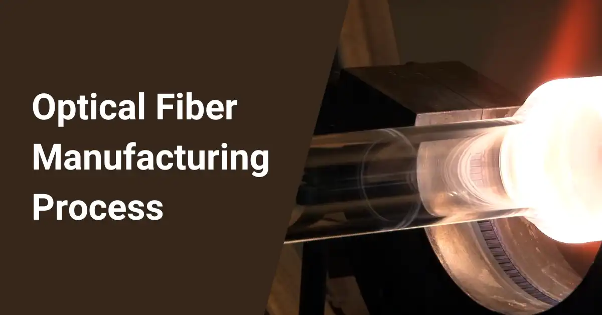
Optical fiber cable carries information encoded in light pulses over long distances with lower signal loss compared to electrical cables. With a 125 μm glass core and 250 μm protective coating, these hair-thin cables are the backbone of global telecommunication networks, allowing broadband data and audio/video transmission.
Adhering to exacting quality standards is paramount when fabricating the optical fiber and protective cable assembly. Consistent precision is required in dimension, composition, and structural integrity to preserve the cable’s light propagation properties.
Table of Contents
Manufacturing Optical Fiber Cable
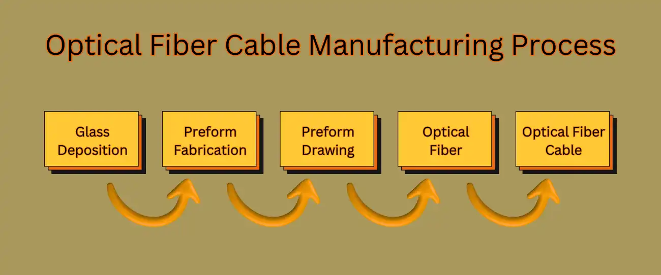
The manufacturing process consists of major steps, including glass deposition, preform fabrication, and fiber drawing, shown schematically below:
| Step | Description |
|---|---|
| Glass deposition | Silica soot is deposited on the inside of a tube from precursor gases via oxidizing reactions |
| Preform fabrication | The soot is vitrified and fused into a large rod with the core-cladding arrangement |
| Fiber drawing | 2000°C softening attenuates the preform while preserving its structure down to 125 μm fiber |
Each step applies specialized techniques to realize the stringent requirements of optical signal transmission over transcontinental distances.
Over 50 parameters spanning temperature, gas flow, rotational speed and deposition rate must align perfectly during the multi-stage manufacture. Consistency of the core refractive index decides the numerical aperture and light acceptance angle of the completed optical fiber cable.
Glass Deposition – Constructing Purity Atom by Atom
The vapor deposition process deposits silica glass from volatile precursors like silicon tetrachloride (SiCl₄) reacting with oxygen:
\( SiCl_4(g)+O_2(g)\rightarrow SiO_2(s)+2Cl_2(g)\)
Deposition occurs in a closed quartz glass tube, which is rotated and heated externally to form high-purity layers of doped silica glass soot on its inner surface:
| Parameter | Typical Value | Role |
|---|---|---|
| Temperature | < 1800°C | Oxidation efficiency |
| Pressure | 1000 – 2000 Pa | Precursor diffusion rate |
| Rotation speed | 5 – 15 rpm | Deposition uniformity |
| Translation rate | 5 – 10 cm/min | Layer thickness |
Germanium chloride and phosphorous oxychloride are introduced to create soot layers with gradations in the refractive index. Adhering to stringent process control minimizes trapped air bubbles and inhomogeneities.
Preform Fabrication – Sculpting the Refractive Index
Preforms replicate optical fiber dimensions and structure on a larger scale with lower precision tolerances for the drawing process:
| Parameter | Preform | Fiber |
|---|---|---|
| Diameter | 10 – 20 mm | 125 μm |
| Length | 50 – 100 cm | 50 – 250 km |
| Core circularity | > 95% | > 99.5% |
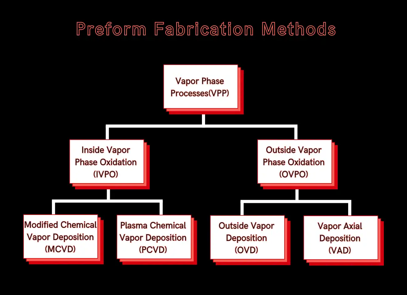
Different deposition processes are customized based on production scale:
- MCVD offers flexibility for specialty fiber R&D with lower material efficiency.
- PCVD enhances deposition rate and achieves radial dopant profiles.
- OVD allows large preform dimensions with thick deposits.
- VAD allows continuous preform growth for maximum productivity.
The porous glass soot deposits are vitrified into solid glass perform rods matching the desired fiber’s refractive index distribution through intermediate steps:
- Sintering – Removes voids forming 95% dense clear porous glass.
- Collapsing – Further heating vitrifies the preform into an amorphous glass rod.
- Dehydration – Drying and chlorine treatment removes hydroxyl impurities.
- Consolidation – Final repeated furnace heating sets dopant levels.
Modified Chemical Vapor Deposition (MCVD) – Precision Crafting with Fire
The Modified Chemical Vapor Deposition (MCVD) process was developed in 1974 at Bell Labs to improve traditional Chemical Vapor Deposition (CVD) methods for fabricating optical fibers.
In MCVD, a quartz tube is used as the initial substrate or source material. Reaction gases such as silicon tetrachloride and germanium tetrachloride are fed into one end of the quartz tube, as shown below.
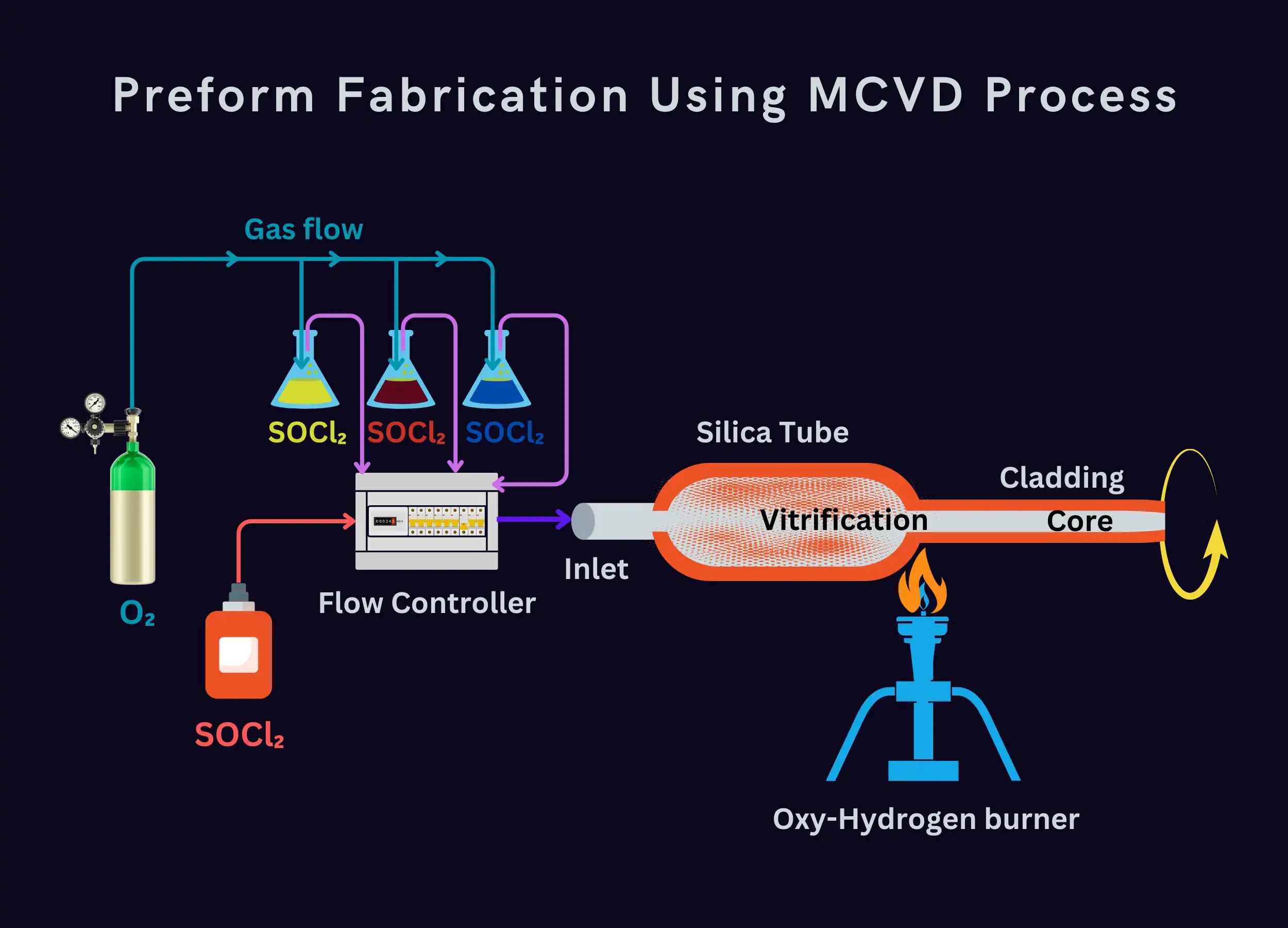
Flame burners are then utilized to locally heat specific regions of the quartz tube from the outside. This directs the heat in a localized manner inside the tube. The heat causes the input gases to decompose and react to form silica and other dopants in gaseous form inside the quartz tube through chemical reactions.
As the gaseous reactants diffuse across the tube, they are deposited and condense on the inner surface of the quartz tube to form thin glass layers. Repeated passes of the burner allow the building up of multiple varying layers to form the finished preform.
MCVD enables the refined deposition of high-purity and doped layers for optical fiber fabrication inside the quartz tube by utilizing localized and controlled heating with flames instead of a tubular furnace.
MCVD allows flexible and precise control over the preform fabrication process for specialty optical fiber design and research:
- An oxy-hydrogen torch traversing along a rotating silica tube locally heats it up to 1900°C to deposit glass soot layers.
- SiCl
₄ , O₂ , and dopant precursors are steadily fed into the tube simultaneously to produce doped silica particles. - The soot reacts and condenses into glass in a single-step deposition and vitrification, building up multiple layers.
Key parameters optimized for a high purity, flawless preform:
| Parameter | Typical Value | Effect |
|---|---|---|
| Torch speed | 5 – 15 cm/min | Radial temperature profile |
| Rotation rate | 5 – 15 rpm | Circumferential uniformity |
| Gas flow rates | 10 – 100 SCCM | Stoichiometry, doping |
| Layers deposited | 100 – 1000 | Core/cladding dimensions |
Final preform dimensions are achieved by collapsing and fusing the hollow fine glass tube into a solid rod with repeated torch passes.
Plasma Chemical Vapor Deposition (PCVD) – Vapor Phase Sculpting
Plasma Chemical Vapor Deposition (PCVD) is a thin film deposition technique used to manufacture optical fibers. PCVD is similar to conventional Chemical Vapor Deposition (CVD) but uses plasma instead of heat to react and decompose the source gases.
In PCVD, precursor gases like silicon tetrachloride and germanium tetrachloride are introduced into a quartz tube. Microwaves are then used to excite the gases and generate a plasma inside the tube, as shown below. The plasma contains highly reactive particles that break down the source gases and cause the released silicon, germanium, and other elements to deposit onto the inner surface of the quartz tube.
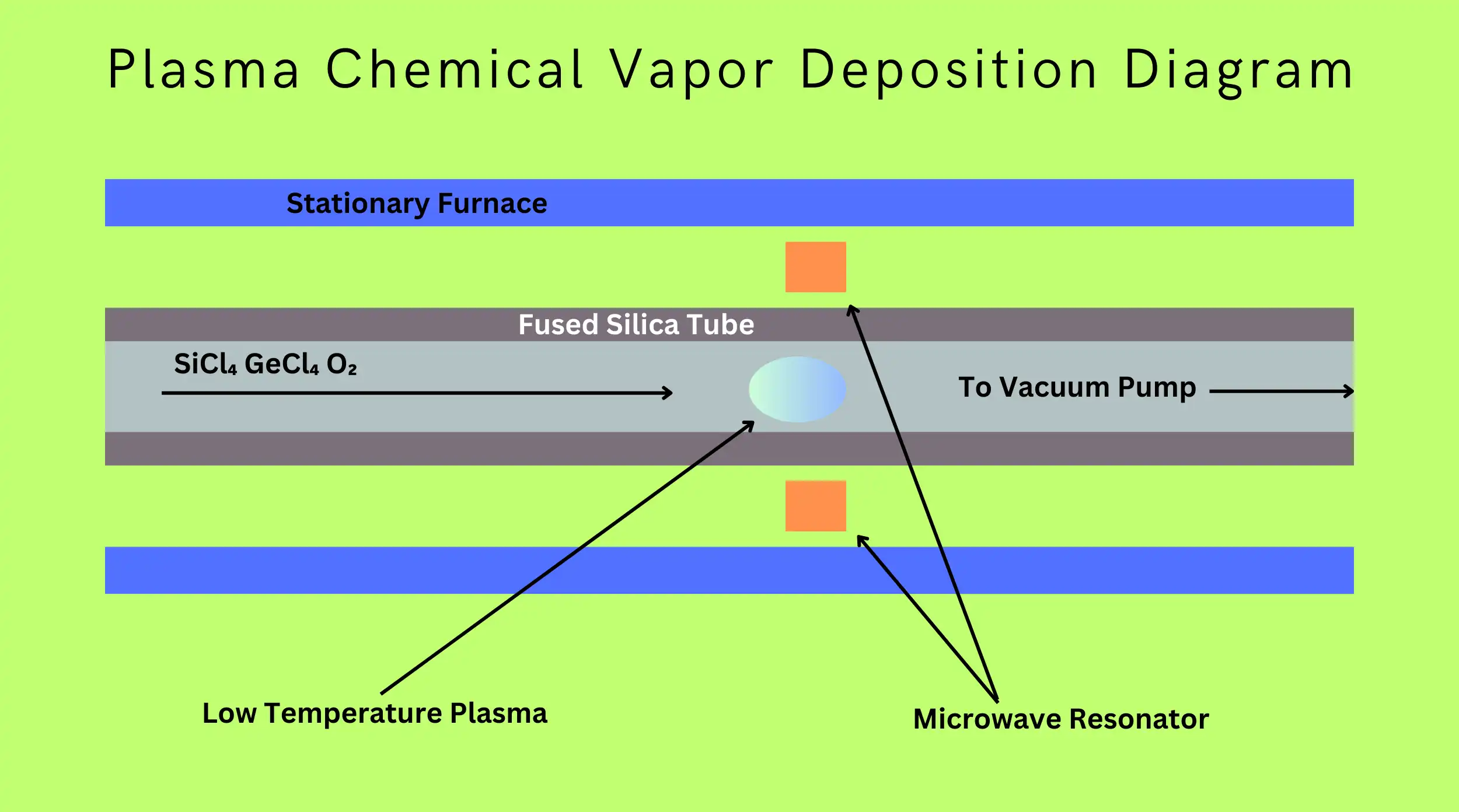
Plasma torches provide localized heating and allow deposition to occur at lower temperatures compared to traditional CVD. This helps reduce unwanted Hydroxide (OH) impurities from being incorporated into the deposited film. Through PCVD processes, transparent and doped core and cladding layers can be deposited to form optical fibers with tailored transmission properties.
Using plasma excitation instead of heat, PCVD allows better control of the deposition conditions and helps fabricate high-quality films for applications such as optical fibers.
PCVD enhances the deposition rate by an order of magnitude using microwave plasma:
- A resonant cavity surrounds the silica tube and couples 2.45 GHz microwaves to ignite the plasma.
- The high-density plasma provides localized extreme heating exceeding 20000°C.
- Excited precursor species diffuse and react rapidly on the tube surface to deposit ultrafine soot.
There are several plasma techniques inside vapor-phase oxidation deposition.
- Plasma CVD
- Conventional plasma CVD uses radio frequency (RF) or microwave frequency electromagnetic fields to ignite and sustain plasma. This dissociates reactant gases, producing surface reactions and uniform thin film depositions.
- Plasma Enhanced CVD (PECVD)
- Similar to plasma CVD but operates at lower temperatures. This reduces thermal stress while retaining reactivity due to plasma. Allows deposition on temperature-sensitive materials.
- Plasma Impulse CVD (PICVD)
- Applies high voltage pulses to locally heat surfaces. Each brief, intense plasma pulse flash evaporates precursors, depositing thin films with unique non-equilibrium microstructures.
- Surface Plasma CVD (SPCVD)
- The plasma is constricted only near the deposition surface in this technique. This enhances chemical precursor activation locally for lower-temperature depositions. Provides radical and ionic tuning of film growth.
Key benefits of PCVD:
- Faster and more efficient with 100% precursor conversion.
- Lower impurity content from the closed reaction chamber.
- Radial plasma distribution assists novel fiber structures.
- Permits use of less volatile and exotic precursors.
Drawbacks include limited deposition lengths and radial non-uniformities requiring optimization.
Outside Vapor Deposition (OVD) – Building Up Glass from the Outside
The Outside Vapor Deposition (OVD), also called flame hydrolysis deposition (FHD) process, is used to manufacture optical fiber preforms through the deposition of thin film layers on the outer surface of a cylindrical core rod.
In OVD, a cylindrical rod or mandrel made of a material like metal or graphite is used as the core. This rod acts as the support for the preform layers and can be extracted at the end of the deposition process.
The key process involved is “flame hydrolysis,” where reactant gases are exposed to a burner flame. As seen in the figure, the gases like silicon tetrachloride (SiCl₄) and oxygen pass through the flame. This causes hydrolysis reactions that break down the gases into reactive intermediates, including silicon monoxide.
These gaseous reactants then deposit and condense as thin film layers of glass, such as silica, on the outer surface of the core rod. Repeated passes allow the building up of multiple concentrically layered structures.
Dopant gases can also be included to dope the deposited films. The resultant multilayered glass structure accumulated on the rod forms the fiber preform through the OVD process.
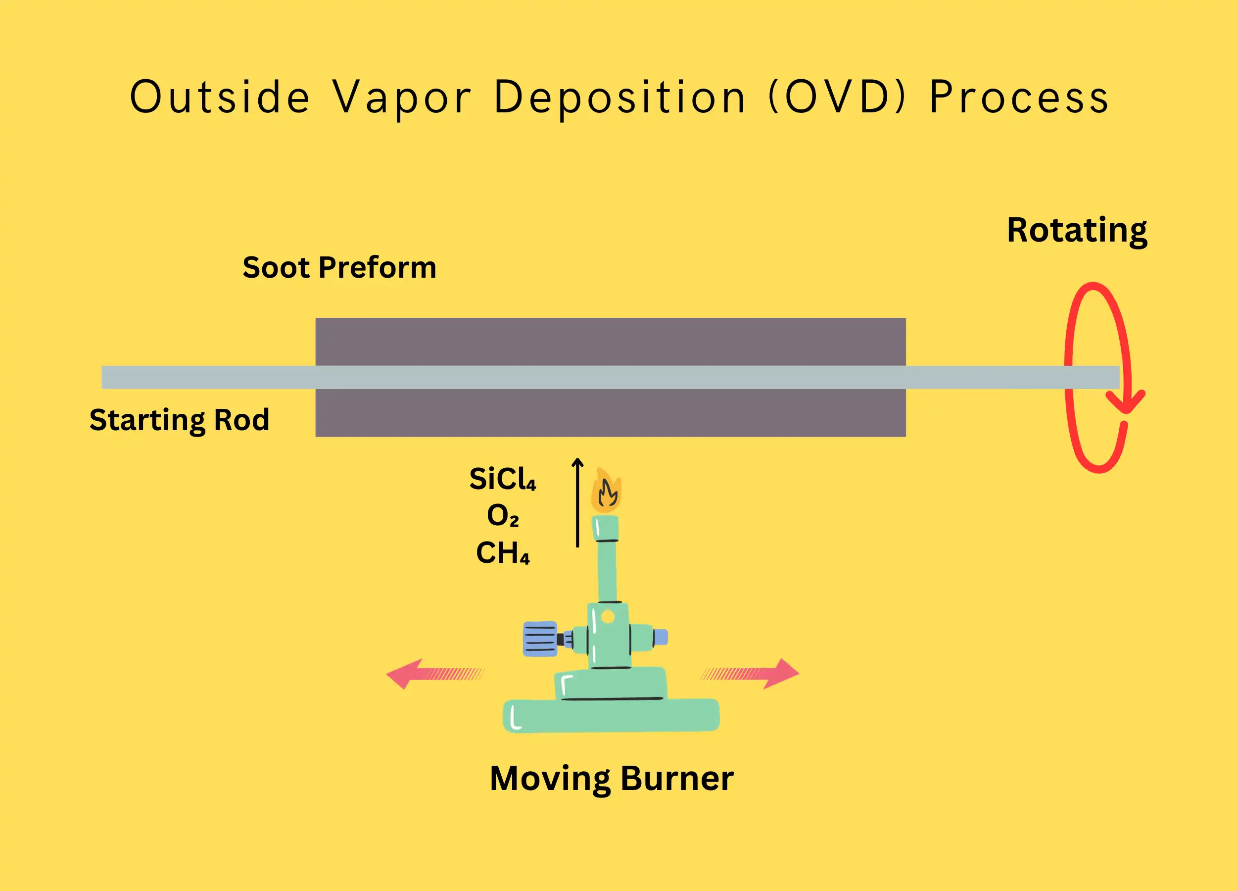
OVD grows glass soot on a solid rotating bait rod using an oxidation flame:
- Precursor gases like SiCl
₄ and GeCl₄ are fed into a hydrogen-oxygen torch to produce silica and Germania microparticles in the flame. - The rotating bait rod collects these tiny molten droplets, building up a porous soot deposit layer by layer.
Key benefits of OVD:
- Allows large preform dimensions with very thick deposits.
- The composition can be varied by changing precursor flow rates.
- Axisymmetric or asymmetric structures can be fabricated.
Intermediate steps transform porous soot into transparent glass:
- Dehydration with Cl
₂ removes water to under 1 ppm. - Sintering in an induction-heated muffle densifies fusing particles.
- Consolidation sets the final refractive index profile.
Vapor Axial Deposition (VAD) – Building the Longest Preforms
Vapor Axial Deposition (VAD) is an important process that is widely used for large-scale production of optical fiber preforms.
Unlike OVD, where deposition occurs radially on a rod, in VAD, the deposition happens axially. VAD involves three main phases:
- Deposition: Gases like silicon tetrachloride (SiCl₄) are injected into a deposition furnace from the top, as shown in below. The gases undergo pyrolysis reactions in the high-temperature zone inside the furnace. This results in the deposition of glass layers (e.g., silica) in the axial direction onto a starting core material placed at the bottom.
- Sintering: The deposited layers are heated to high temperatures using the furnace to sinter and densify the glass structure.
- Consolidation: Further heating leads to consolidation of the layered glass structure to form a long cylindrical preform with concentric layers mimicking the fiber design.
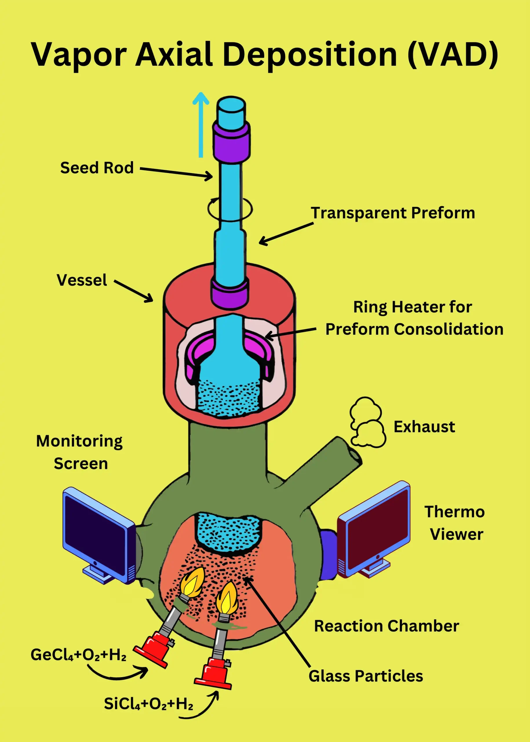
The VAD process enables the fabrication of large preforms suitable for drawing very long lengths of optical fiber, up to 250 km. This continuous one-step process is well-suited for high-volume production compared to OVD.
In VAD, glass deposition occurs along the axis of precursor gas flows, enabling continuous single-step preform growth:
- Reactant gases enter the top of a vertically oriented chamber and traverse downwards.
- Porous soot deposits on a seed rod suspended from a microbalance on the chamber top.
- The growing soot preform is extracted slowly through the bottom to make way for fresh deposition.
Benefits of VAD:
- Continuous operation to produce preforms up to 300 kg.
- Drawing such a preform makes 250 km of optical fiber.
- A closed chamber permits ppb-level dehydration.
Differences between MCVD, PCVD, OVD, and VAD methods
Here is a comparison chart of the major differences between MCVD, PCVD, OVD, and VAD preform fabrication methods:
| Parameter | MCVD | PCVD | OVD | VAD |
|---|---|---|---|---|
| Deposition Mechanism | Flame hydrolysis | Microwave plasma | Flame hydrolysis | Flame hydrolysis |
| Heat Source | Oxy-hydrogen torch | Electromagnetic waves | Oxy-hydrogen torch | Oxy-hydrogen torch |
| Deposition Surface | Tube interior | Tube interior | Bait rod exterior | Suspended rod |
| Throughput | Low | Medium | High | Highest |
| Dopant Control | Excellent | Very Good | Good | Good |
| Cost | High | Medium | Low | Lowest |
| Fiber Type | Specialty | Specialty | Standard | Standard |
| Preform Size | Small | Small | Very Large | Large |
| Hydroxyl Content | Low | Very Low | High | Low |
In summary:
- MCVD offers superior compositional control for specialty fibres
- PCVD enhances deposition rate using plasma
- OVD builds preforms externally with fewer constraints
- VAD allows continuous single-step preform production
Optical Fiber Drawing – Spinning Glass from Rock into Silk
The preform is precisely attenuated from millimeter dimensions down to 125 μm diameter fiber optic strand in a high-temperature drawing tower:
- Preform tips are heated to over 2000°C in a precision-controlled furnace to soften glass.
- The molten tip flows down by gravity and can be drawn into the fine fiber at speeds exceeding 10 m/sec.
- Fiber diameter must accord within ±0.1 μm of the 125 μm standard to meet optical transmission norms.
- To achieve this consistency, a laser micrometer dynamically gauges and feeds back size variations to control preform feed and draw rates.
- The bare fiber passes through the molten ultraviolet curable polymer to apply a protective 250 μm coating.
The resulting drawn fiber retains exactly the core-cladding refractive index profile dictated by preform composition and structure. This upholds the designed single or multimode transmission properties needed for communication systems.
Summary
Realizing low-loss optical signal transmission demands fiber consistency along kilometers of cable length. Maintaining identical performance specs between fabrication batches is also vital for network deployments.
The production process executes a dimensional reduction by five orders of magnitude, while preserving materials purity and optical characteristics. Each step plays a unique role – vapor deposition defines the composition, preforms enable scaling, and drawing provides product continuity.
By coordinating process parameters across temperature, pressure, flow rates, and tool design, high-fidelity replication of the preform template is sustainable in long fiber lengths. Understanding the synthesis mechanisms and dynamics provides opportunities for specialized fiber innovation too.
FAQ
What are the raw materials for optical fiber?
Silicon dioxide (SiO₂) is the primary raw material for optical fibers, often with small amounts of other chemicals added to enhance properties. Silicon tetrachloride is also used in the production of optical fiber preforms.
What is the core of a fiber optic cable made of?
The core, where light travels, is usually made of doped silica with a higher refractive index than the cladding for internal reflection.
What is the most commonly used optical material?
Pure silica (SiO2) is the most commonly used material for optical fibers due to its abundance, low cost, excellent transmission properties, and chemical stability.
What cuts fiber optic cable?
∎ Cleaving tools: These tools score and snap the fiber, creating a smooth and perpendicular end face for optimal light transmission. They come in various types, including manual cleavers, automated cleavers, and fusion splicers with integrated cleaving functions.
∎ Diamond scribers: A fine diamond tip can score the fiber, followed by gentle pulling to achieve a clean break. This method is less precise than using dedicated cleaving tools but can be useful in field applications.
∎ Laser cleaving: High-powered lasers can vaporize a small portion of the fiber, creating a clean and precise cleaved end. This method is often used in automated production lines for its speed and accuracy.
Which are the six main parts of optical fiber?
A typical fiber optic cable has six components:
∎ Core: Carries the light signal.
∎ Cladding: Surrounds the core, reflecting light back into it.
∎ Primary Coating: Protects the core and cladding from scratches.
∎ Secondary Coating (optional): Provides additional mechanical and environmental protection.
∎ Strength Members: Increase cable tensile strength and crush resistance.
∎ Outer Jacket: Protects the cable from external damage.