This calculator helps you estimate the total attenuation (signal loss) in a fiber optic cable link. Here are the details and instructions about each field and how they contribute to the calculation:
1. Attenuation Coefficient (dB/km):
- This value represents the inherent signal loss per kilometer of fiber optic cable.
- It depends on the cable type (e.g., multi-mode, single-mode) and the wavelength of light used.
- You can select standard predefined values or enter your own.
- The calculator provides pre-defined values for common scenarios
- Here are the standard values of the attenuation coefficient for different fiber optic cable types
| Cable Type and Wavelength | Fiber Attenuation (dB/km) |
|---|---|
| Multi-Mode – 850nm | 3 dB/km |
| Multi-Mode – 1300nm | 0.8 dB/km |
| Single Mode – 1310nm | 0.4 dB/km |
| Single Mode – 1550nm | 0.2 dB/km |
2. Cable Length (km):
- This is the physical length of the fiber optic cable in kilometers.
- The longer the cable, the greater the inherent attenuation due to the attenuation coefficient.
3. Number of Connectors:
- Connectors are used to connect fiber optic cables.
- Each connector introduces some insertion loss, which contributes to the overall attenuation.
- The calculator considers the number of connectors used in the link.
4. Connector Loss (dB/connector):
- This value represents the typical insertion loss caused by a single connector.
- The pre-defined attenuation coefficient values might include an average connector loss, or you can enter a specific value if known for your connectors.
- Here are the standard values of the connector loss for different fiber optic cable types
| Cable Type | Connection Loss (dB) |
|---|---|
| Multi-Mode – Single Fiber | 0.5 dB |
| Multi-Mode – Array (12/24) | 0.75 dB |
| Single Mode – 1310nm | 0.5 dB |
5. Number of Splices:
- Splices are permanent joints connecting two fiber optic cables.
- Similar to connectors, splices also cause some insertion loss.
- The calculator considers the number of splices in the link.
6. Splice Loss (dB/splice):
- This value represents the typical insertion loss caused by a single splice.
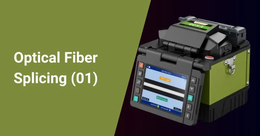
- Similar to connector loss, pre-defined values or a custom value for your specific splice type can be used.
- Here are the standard values of the splice loss for different fiber optic cable types
| Cable Type | Splice Loss (dB) |
|---|---|
| Multi-Mode | 0.3 dB |
| Single Mode | 0.15 dB |
Calculate Button:
- Clicking this button triggers the calculation based on the input values.
- Also, you can reset all the fields by clicking the reset button.
Total Attenuation (dB):
- This is the calculated result displayed after clicking “Calculate.”
- It represents the estimated total signal loss in decibels (dB) across the entire fiber optic link.
How this calculation works
The calculator essentially performs the following calculation:
Total Attenuation (dB) = (Attenuation Coefficient * Cable Length) + (Number of Connectors * Connector Loss) + (Number of Splices * Splice Loss)
By entering the relevant values, you can estimate the total signal loss in your fiber optic link and assess if it meets your transmission requirements.
Additional Considerations:
- This is a simplified model and might not account for all factors affecting attenuation, such as cable aging, environmental conditions, and bending losses. You need to consider those factors also.
- We recommended that fiber optic cable specifications and component datasheets be consulted for accurate loss values.
- For critical applications, consider using an Optical Time Domain Reflectometer (OTDR) for a more precise measurement of actual attenuation in a deployed fiber optic link.


