When optical signals (pulses) are sent through optical fibers, different frequency components or different mode components move at different speeds, and signal distortion (pulse broadening) will always happen after a certain distance.
We use the term “dispersion” in optical fibers to describe this effect. The optical signal sent through the optical fiber has a specific spectrum width, which means that the optical signal has many different frequency components.
At the same time, an optical signal in multimode fiber can be made up of more than one mode. This means that each frequency component can also be made up of more than one mode component.
Ultimately, we can define this as “dispersion is the broadening of the input pulse in time as it propagates through the fiber.”
Table of Contents
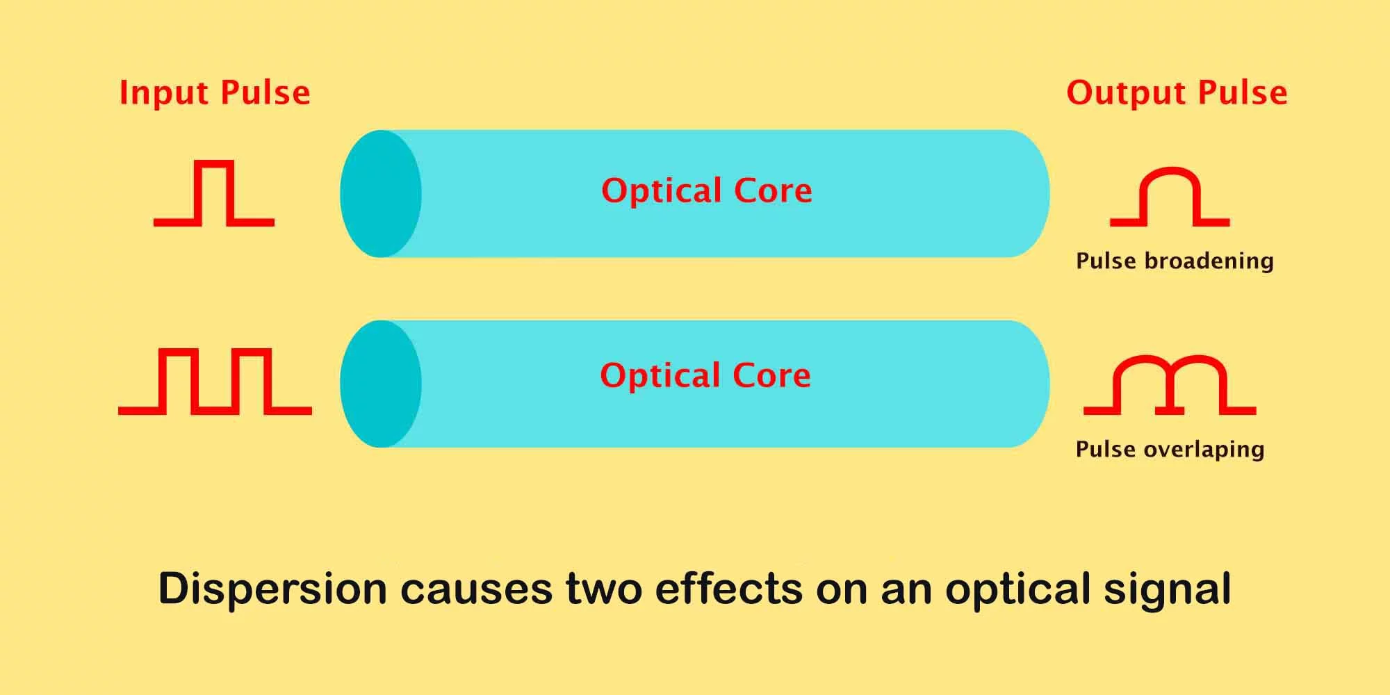
Dispersion causes two effects on an optical signal.
- Pulse broadening
The perfect light pulse emits at the beginning, and after it travels long distances, like 2000m in the optical fiber, the pulse becomes wide.
- Bit error
Because of the pulse broadening, each pulse overlaps at the end of the optical fiber. Since the detector couldn’t identify the overlapped pulses, there will be a bit error in the optical signal.
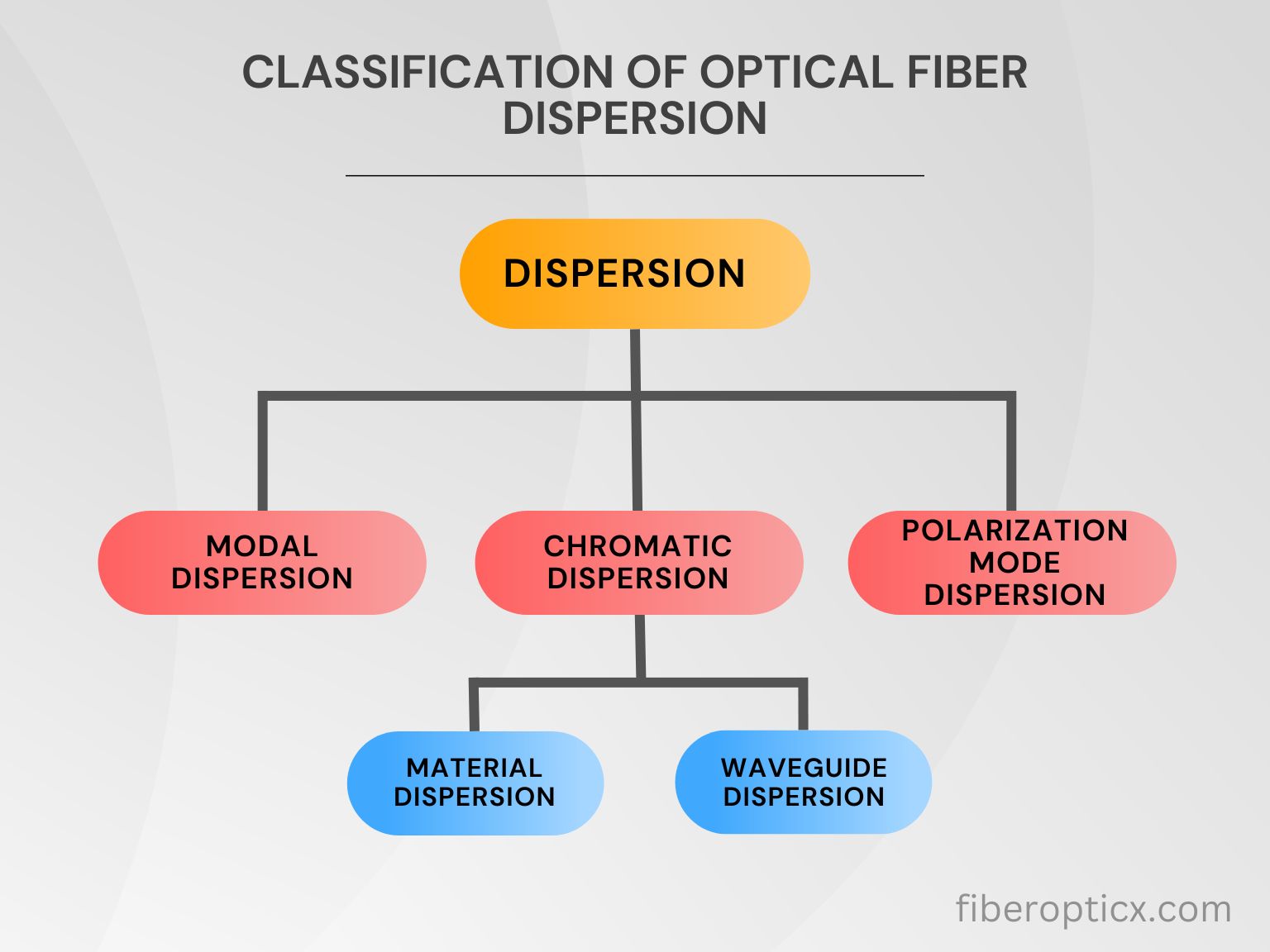
Classification of optical fiber dispersion
Optical fiber dispersion distorts the transmitted signal pulse. That will lead to limits on the capacity and bandwidth of optical fibers.
We can divide optical fiber dispersion theoretically into the main categories.
- Modal dispersion
- Chromatic dispersion
- Polarization mode dispersion
The modal dispersion is only on the multimode fibers, which sets them mainly separated from single-mode fibers.
Modal dispersion in optical fiber
Modal dispersion is a signal distortion process that occurs in multimode fibers. It is also called intermodal dispersion. Light entering the fiber at different angles takes a different path or mode in multimode fiber.
Thus, due to the different transmission paths of each mode, its transmission speed or group velocity also varies. Hence, there is a time difference between the signal transmission between the modes and the signal’s arrival at the optical fiber end.
The modal dispersion is directly proportional to the transmission path. That is, the modal dispersion caused by the light entering a larger angle with a longer distance is higher than that caused by the light entering a smaller angle with a shorter distance.

Multimode fibers can transmit up to 17 modes of light propagation simultaneously. Hence, its dispersion is much higher than single-mode fiber. This is because single-mode fibers have a single propagation mode. Light travels along the core without being reflected at the cladding boundary, so there is no modal dispersion.
Try out our fundamental modal dispersion calculator here
Chromatic dispersion in optical fiber
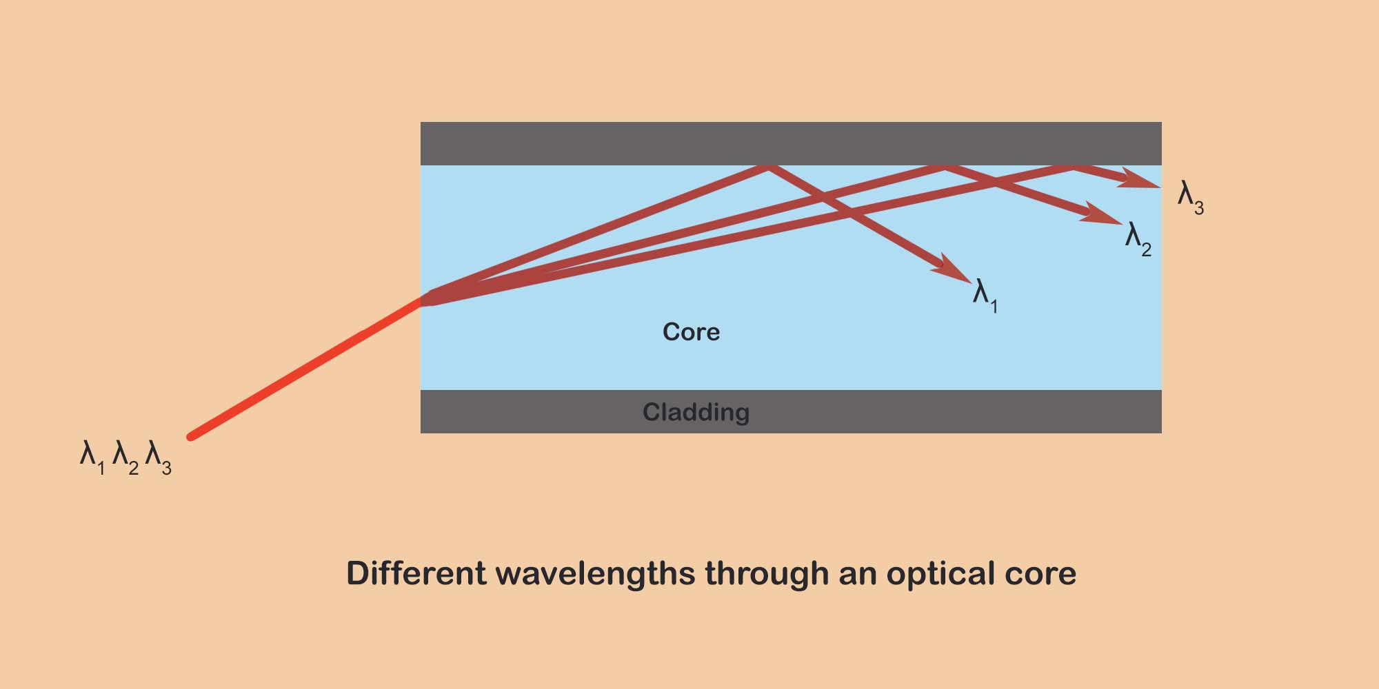
Chromatic dispersion occurs in all types of fibers. This dispersion occurs because different colors or frequencies of light behave slightly differently when passing through a medium such as glass. The core and cladding in fiberoptics have different refractive index materials, causing light wavelengths to travel slower or faster than others.
We can divide chromatic dispersion into two types according to the reasons for dispersion.
- Material dispersion
- Waveguide dispersion
Material dispersion in optical fiber
Material dispersion occurs because the refractive index of the silica used to make optical fibers is frequency-dependent. Different frequency components or different wavelengths of light travel at different speeds in silica.
This phenomenon is called material dispersion. The material dispersion of a fiber depends on the material’s refractive index, and we cannot change it.
Waveguide dispersion in optical fiber
The light pulse partially travels in the core and partially in the cladding. Here, light travels faster in the core and slower in the cladding. So, the different colors of light travel at different speeds in the core and cladding. This phenomenon is called waveguide dispersion in optical fiber.
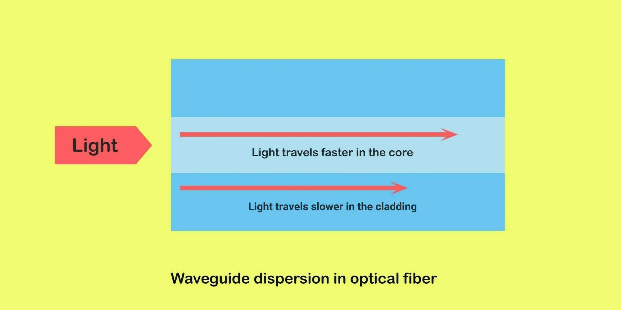
Even though we cannot change material dispersion, we can change the waveguide dispersion in optical fibers. We can change the signal wavelength and able to get zero waveguide dispersion at a specific wavelength.
Polarization mode dispersion in optical fiber
A light pulse is composed of two parts and modes 90 degrees perpendicular to each other. We call them orthogonal. Theoretically, these two modes travel at the same speed. But in reality, external factors affect the traveling speed of these two modes.
Because of these external factors, the two parts of the light pulse travels at different speed and arrive at the end of the fiber at different time. This phenomenon is called polarization mode dispersion or PMD in an optical fiber.
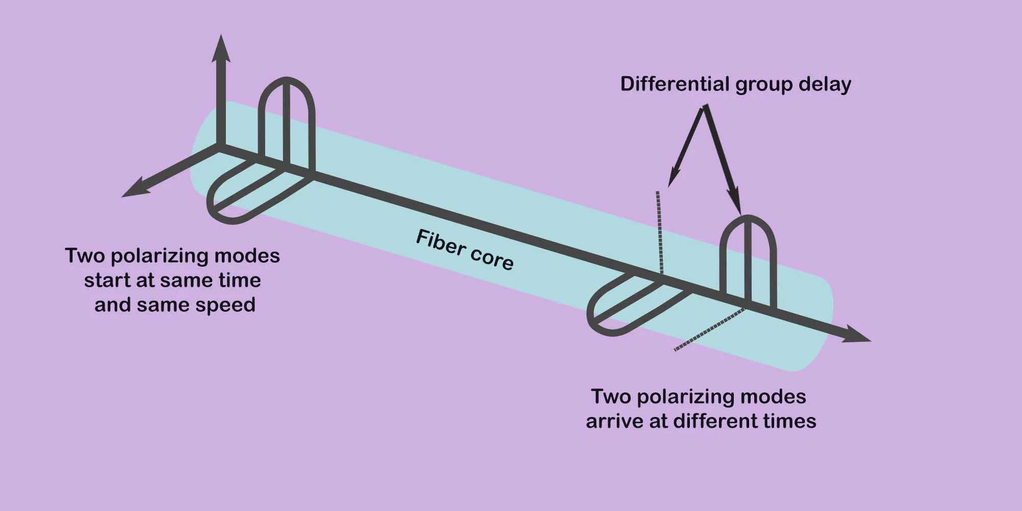
The timing difference of orthogonal that came to the end of the fiber is called differential group delay.
The polarization mode dispersion in optical fiber is caused because by external factors. Fiber core stress, cladding eccentricity, fiber twist, fiber stress, and fiber bend mostly cause polarization mode dispersion.
Dispersion and Bandwidth in Optical Fibers
There are certain factors that limit the information capacity of Optical fibers. Two crucial parameters that restrict data transfer rates over long distances are dispersion and bandwidth.
What is Dispersion and Why Does it Matter?
Dispersion refers to the spreading or broadening of light pulses as they travel down the fiber. The light signals enter the fiber-containing neatly packed data pulses. But as they propagate, the pulses expand and overlap due to dispersion. This leads to distorted signals at the receiving end, increasing bit error rates.
Internodal dispersion plays a major role in limiting bandwidth in multimode fibers. These fibers contain multiple propagation paths that light can take, causing different signal components to reach the end at different times. Reducing intermodal dispersion while manufacturing the fibers is key to enhancing their capacity.
The Importance of Bandwidth
Bandwidth denotes the range of operating frequencies supported by a fiber. It determines how much data the fiber can transmit per unit of time. For example, a bandwidth of 500 MHz would allow data rates of about 5 Gigabits per second.
Higher bandwidth → Higher data transfer capacity
But there’s a tradeoff involved. Light signals get more distorted over longer distances. So we cannot keep increasing bandwidth arbitrarily for very long fiber lengths.
Bandwidth-Length Product – A Key Metric
This brings us to an important metric called the bandwidth-length product. It is defined as:
Bandwidth-Length Product = Bandwidth x Length of Fiber (Typical units – MHz-km)
The bandwidth-length product indicates transmission capacity for a given fiber type. We cannot exceed this limit without seriously compromising signal quality. Table 1 shows typical numbers:
| Fiber Type | Bandwidth-Length Product |
|---|---|
| OM1 Multimode | 200 MHz-km |
| OM2 Multimode | 500 MHz-km |
| OM3 Multimode | 2000 MHz-km |
So, for instance, if using OM2 fiber with the bandwidth of 500 MHz – we could transmit a 500 MHz signal up to 1 km. But the product has already reached the limit of 500 MHz-km. Going beyond 1 km would require lowering the bandwidth to keep the product constant.
Choosing an optimal fiber type and keeping transmission distances moderate is key to utilizing the full information-carrying capacity. Employing dispersion compensation techniques also helps reduce signal distortions. With relentless research advances, the future looks brighter in terms of pushing the boundaries of these limits further out.
Typical bandwidth of different types of multimode fibers
| Fiber Type | Size | Bandwidth (MHz*Km) | |
| Overfilled launch (LED) 850 nm | Effective model bandwidth (Laser) 850 nm | ||
| OM1 | 62.5/125 | 200 | N/A |
| OM2 | 50/125 | 500 | N/A |
| OM3 | 50/125 | 1500 | 2000 |
| OM4 | 50/125 | 3500 | 4700 |
| OM5 | 50/125 | 3500 | 4700 |
Summary
Dispersion induces pulse spreading, impairing bandwidth over fibre spans, necessitating mitigation. Various chromatic, modal, and polarization mechanisms degrade coherence.
Chromatic results from wavelength-dependent refraction, including material differences amplifying phase variances. Waveguide impacts exacerbate as light partitions between core and cladding experience unequal advancement.
Modal dispersion uniquely impacts multimode fibers, divergent pathlengths dispersing modes temporally. Polarization mode variance arises from external asymmetries inducing nonidentical group velocities between orthogonal polarizations.
Pulse distortion introduces overlapping, hampering identification, and provoking bit errors. Classification organizes mitigation strategies, targeting chromatic cancellation at specific wavelengths. Modal demands single-mode adoption, while polarization remediation centers on stress reduction through cabling optimization.
Understanding dispersion origins informs resistance to signal deterioration, preserving clarity even over elongating segments. Improvements in specification bolster capacity across vast interconnectivity by combating coherence degradation.
FAQ
What is dispersion optical fiber?
When light pulses travel through a fiber, it will become wider than it started. This phenomenon is called dispersion in optical fibers.
What are the types of dispersion?
The main types of dispersion are modal dispersion, chromatic dispersion, and polarization mode dispersion.
What is the best example of dispersion?
When white light passes through a glass prism, it splits mainly into seven colors. The same phenomenon occurs when sunlight passes through the water drops, known as a rainbow. So, the rainbow is the best example of natural dispersion.
How dispersion effects optical fiber?
Because of dispersion in optical fiber, may cause pulse broadening or compression. it is the reason for the bit error at the receiver. It will create wrong data at the end of the fiber.