Optical fibers are essential components in modern telecommunication systems. They transmit information over long distances as light pulses. Understanding key concepts like the cone of acceptance, acceptance angle, numerical aperture, mode propagation, and mode field diameter provides insight into fiber optic performance and design. This guide explains these key parameters in simple terms.
Table of Contents
Cone of Acceptance in Optical Fiber
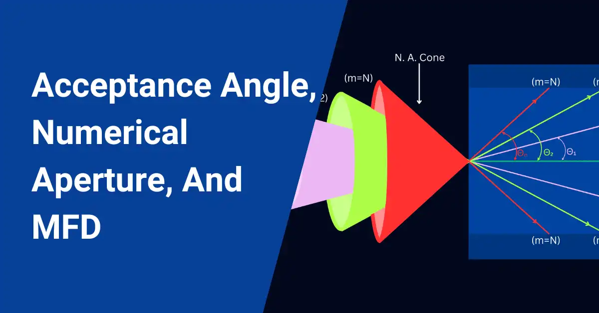
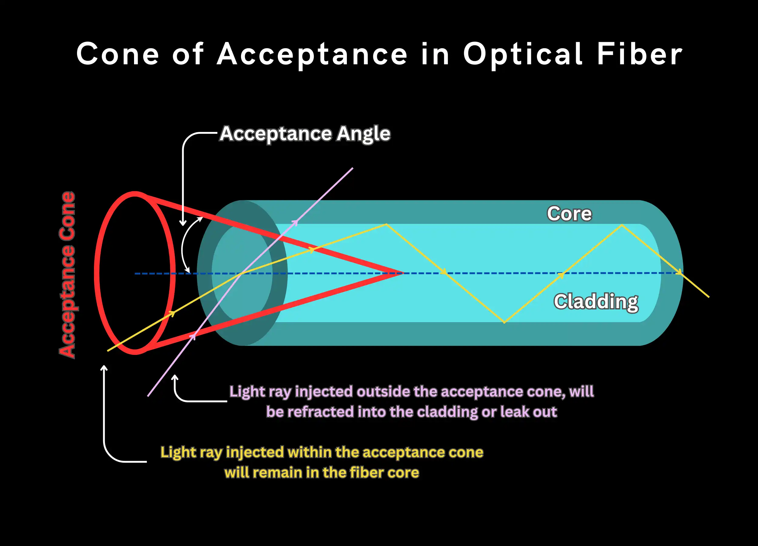
Since optical fiber cores are cylindrical, a geometrical cone exists that determines light entrance to the fiber. This is the cone of acceptance.
- Light entering within the cone stays in the core by total internal reflection.
- Light outside the cone leaks into the cladding or exits the fiber.
The cone angle depends on the core diameter and fiber numerical aperture (NA). A wider cone (larger NA) enables more light propagation in the fiber.
The acceptance angle equals half the maximum incident angle for total internal reflection.
Cone of Acceptance Optical Fiber Formula
The acceptance cone angle is:
\(\Theta a=sin^{-1}(NA)=sin^{-1}(n\Theta/nf)*\sqrt(nf^2-nc^2)\)
Where:
- θa = Acceptance angle
- NA = Numerical aperture
- nΘ = Surrounding medium refractive index
- nf = Core refractive index
- nc = Cladding refractive index
This relates the cone angle to the refractive indices. The larger the acceptance angle, the wider the cone, allowing higher light input.
Typical multimode fiber NA is 0.2-0.3. Single mode is ~0.1. Larger NA fibers accept light over a wider cone.
Matching the incident beam to the acceptance cone profile is key for efficient fiber coupling and minimizing losses.
Acceptance Angle of Optical Fiber
The acceptance angle is the maximum angle at which light can enter the fiber core and still propagate down the length of the fiber. Think of it like a tunnel – there is a maximum angle you can enter the tunnel and still be able to pass through it.
In an optical fiber, the acceptance angle depends on the difference in refractive index between the core and the cladding. The higher the difference, the wider the acceptance angle can be.
A wider acceptance angle means the fiber can accept light from a wider range of angles and bend more tightly without losing that light. But it also means more dispersion of the signals.
The acceptance angle is related to the numerical aperture (NA) of the fiber:
NA = sin(acceptance angle)
So a fiber with NA of 0.2 means the maximum acceptance angle is sin-1(0.2) = 11.5 degrees.
The key points are:
- Acceptance angle is the max input angle for light to propagate
- Wider angle means the fiber accepts more light
- Related to NA and core/cladding refractive index difference
- Balance between gathering more light vs dispersion
What is the Numerical Aperture in Optical Fibers?
The numerical aperture (NA) measures an optical fiber’s ability to gather and transmit light. It indicates how much light the fiber can collect from the source.
A fiber with a higher NA can capture more light for propagation down the core.
There are two key factors that determine the numerical aperture:
1. The Acceptance Angle
This is the maximum angle at which light can enter the fiber and still propagate down the length of the core.
Wider angle = fiber can accept more light.
2. The Refractive Index Difference
This is the difference between the core and cladding refractive index.
Higher difference = fiber can confine more light in the core.
How is Numerical Aperture Related to These Factors?
The numerical aperture (NA) is defined as:
NA = sin(acceptance angle)
It’s also related to the refractive indices:
\(NA=\sqrt(n1^{2}-n2^{2})\)
Where:
n1 = core refractive index
n2 = cladding refractive index
So the NA depends directly on the acceptance angle and the refractive index difference.
For your calculations try our Numerical Aperture calculator from here
What Does a High or Low NA Mean?
- High NA (~0.3) = fiber gathers more light but has a higher dispersion
- Low NA (~0.1) = less light gathering but lower dispersion over distance
Multimode fiber needs higher NA. Single mode can have lower NA.
Why Use Small Numerical Aperture for Long Distance Communication?
Small NAs around 0.1-0.2 are best for long-haul fiber links because:
- Reduces dispersion – maintains signal integrity over distance
- High accuracy and precision
- No interference effects like mode coupling
- Enables very high data transmission capacity
- Used in single-mode fibers designed for long-distance
The tradeoff is more difficult coupling into the small NA fiber core.
What Numerical Aperture for Short Distance?
For short-reach applications, multimode-graded index fibers with NA of 0.29-0.3 are commonly used.
- Multimode fibers accept multiple propagation paths.
- The higher NA gathers more light.
- Short-distance fiber minimizes modal dispersion effects.
So, multimode fiber with higher NA suits short, high-bandwidth connections like data centers.
Key Properties Related to NA
- Higher NA = More Light Gathering: A wider acceptance cone means more light enters the fiber core.
- Higher NA = Tighter Bending: Fiber with high NA can bend into smaller radius loops before signal losses occur.
- Multimode vs Single Mode: Typical multimode fiber NA is 0.2-0.3, while single mode is ~0.1. Multimode needs higher NA.
- More Modes with Higher NA: In a multimode fiber, higher NA supports more guided optical paths or modes.
- Higher NA = More Dispersion: The larger number of modes in a high-NA multimode fiber leads to increased signal dispersion.
- Attenuation Tradeoff: Higher refractive index contrast and NA in single-mode fibers increases dopant levels, raising attenuation.
Mode Propagation in Optical Fiber
When light travels in free space like air, it propagates as a continuous wave. However, when this same light enters an optical fiber, it interacts with the fiber’s core and cladding materials. This interaction changes the behavior of the light.
Instead of remaining a single continuous wave, the light inside the fiber splits up into multiple separate beams called modes. Think of a mode as a unique bouncing pattern or path that the light follows down the length of the fiber.
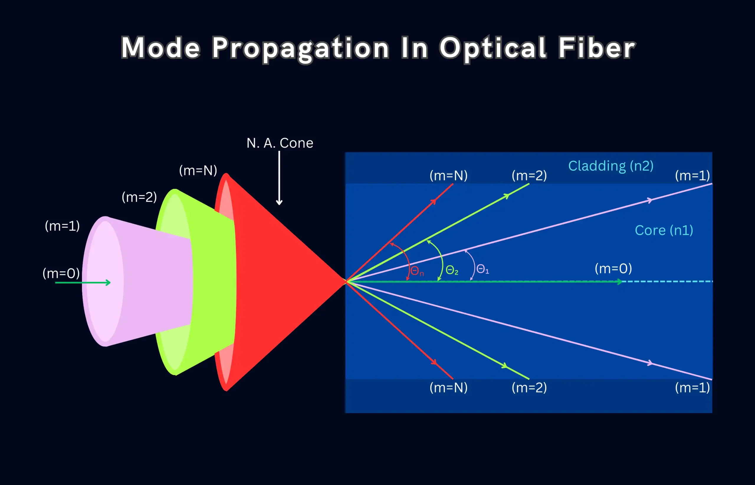
The number of possible modes depends on the fiber properties. In a multimode fiber, there can be hundreds or thousands of different mode paths. Each mode takes a different angle path down the core, creating a unique “bouncing” pattern.
On the other hand, a single-mode fiber is designed to only support one mode – a single straight path down the core. No matter what angle the light enters, it is confined to this fundamental mode.
The modes collectively create the total light intensity distribution or pattern within the fiber core. Multimode patterns are complex, while single-mode fibers have a simple Gaussian profile.
The key points are:
- Light goes from continuous to discrete modes inside the fiber
- Each mode is a separate beaming path through the core
- Multimode = many modes, single mode = only one mode
- Modes create the overall light intensity pattern in the fiber
Here is the comparison of different modes in optical fiber.
| Single Mode | Multimode | |
|---|---|---|
| Attenuation | Low | Higher |
| Dispersion | Low | High |
| Cost | High | Lower |
| Applications | Long distance | Short distance |
Single mode has lower losses for long distances. Multimode suits cost-effective short-reach links.
Mode Field Diameter
The mode field diameter (MFD) represents the actual diameter or spread of light within an optical fiber. Even though most light travels through the core, some of it extends slightly into the inner cladding region.
The MFD measures the spatial width of this light intensity pattern. It’s basically the fiber’s “effective core size” including the core and a portion of the cladding that carries light.
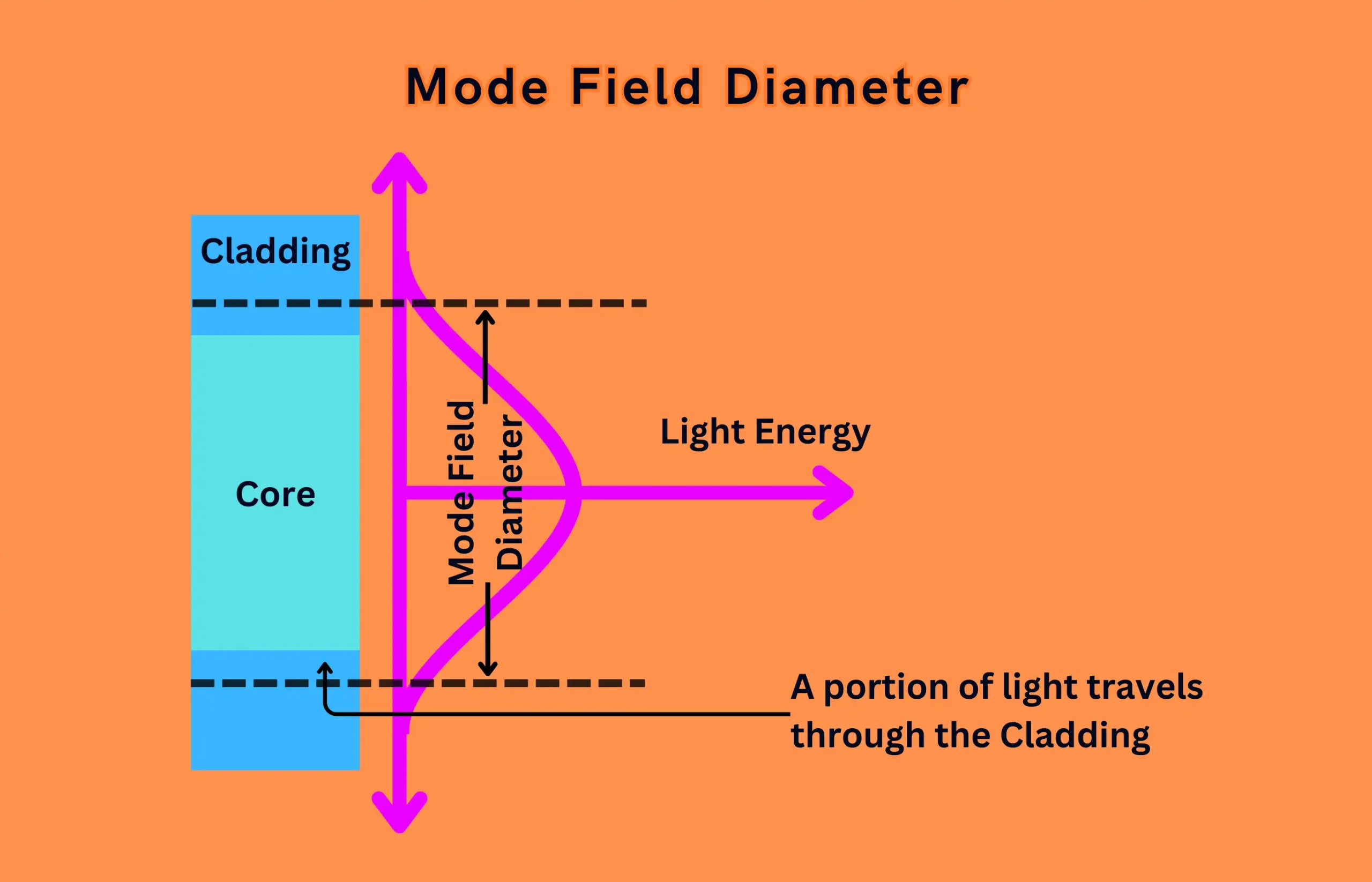
You can simply calculate the mode field diameter here
For single-mode fibers, the MFD matters because:
- It’s larger than just the physical core size
- Affects losses when fibers are spliced or coupled to sources
- Impacts how much light leaks out during fiber bends
- More useful than core diameter alone for estimating performance
The MFD isn’t as important for multimode fibers carrying many guided modes within the core.
So in summary:
- MFD is the diameter of the light spread within the fiber
- Extends slightly beyond just the core into the cladding
- Key parameter for estimating splice/bend loss in single-mode fibers
Summary
Key optical fiber concepts like acceptance cone, numerical aperture, mode types, and mode field diameter relate to fiber performance. Understanding these parameters provides insight for fiber optic link design and optimization. Matching source characteristics like wavelength and divergence to fiber parameters enables efficient light propagation and minimizes losses.
FAQ
What is TIR in optical fiber?
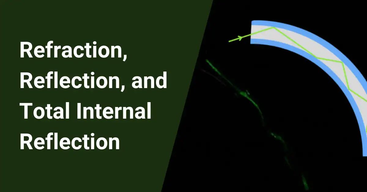
TIR stands for Total Internal Reflection, a critical phenomenon in optical fibers. When light enters the fiber core at an angle exceeding the critical angle (determined by the refractive indices of core and cladding), it undergoes TIR, bouncing back and forth within the core due to repeated reflections, guiding the light signal along the fiber.
What is the nominal mode field diameter?
The nominal MFD is a standard value specified by the fiber manufacturer, representing the expected diameter of the fundamental mode within the fiber. It’s often used for design purposes and coupling calculations.
Is mode field diameter (MFD) the same as spot size?
While related, they’re not identical. MFD defines the area within the fiber where most light travels, typically a circular shape. Spot size refers to the focused beam diameter at the fiber output, which can be slightly larger than the MFD due to diffraction. But, in many cases, their values are comparable.
What is the typical numerical aperture (NA) for a 50/125 μm optical fiber?
For a standard 50/125 μm multimode fiber, the typical NA ranges from 0.20 to 0.29. This range indicates a good balance between light collection and manageable dispersion for short-distance applications like data transmission within buildings.
What is the difference in NA between single-mode and multimode fibers?
Single-mode fibers, designed for long-distance, low-dispersion communication, have much smaller NAs (around 0.10-0.13) compared to multimode fibers (0.20-0.30). This trade-off ensures minimal dispersion in single-mode fibers but requires more precise light coupling due to their narrower acceptance angles.


